
Leon Mk2
| I - Assembly overview of strut, stabilizer bar and swinging arm from year 2001 models onwards |
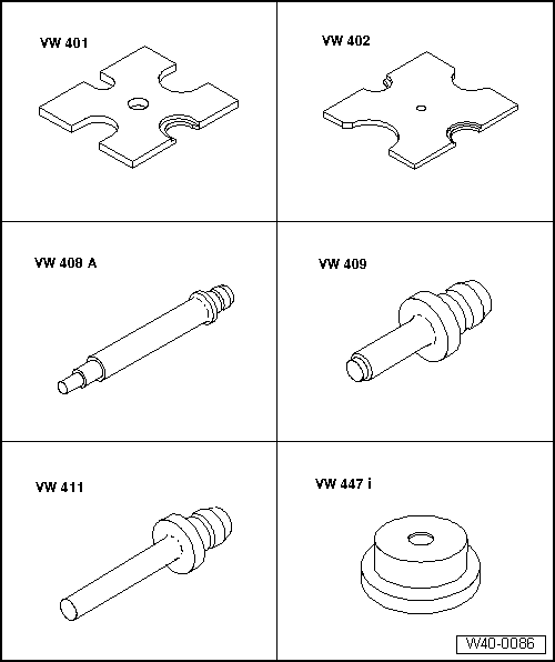
| Special tools and workshop equipment required |
| t | Pressure plate -VW 401- |
| t | Pressure plate -VW 402- |
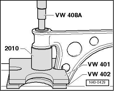
| t | Terminal crimper -VW 408 A- |
| t | Terminal crimper -VW 409- |
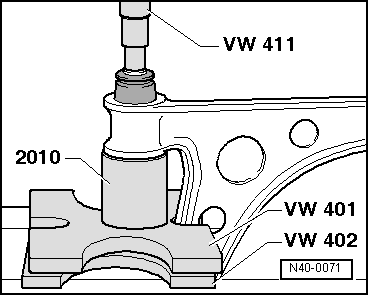
| t | Terminal crimper -VW 411- |
| t | Pressure plate -VW 447 i- |

| t | Release pipe -30-14- |
| t | Supplement -40-103- |
| t | Tubular part -2010- |
| t | Tubular part -3146- |
| t | Torque wrench -V.A.G 1331- |
| t | Torque wrench -V.A.G 1332- |
 Note
Note| t | If a vehicle needs to be moved after the driveshaft has been removed, an outer joint must first be fitted in place of the driveshaft and tightened to 50 Nm to prevent damaging the wheel bearing. |
| t | No welding or straightening work can be done on the support and guide elements of the suspension system. |
| t | Always replace self-locking nuts following their removal. |
| t | Always replace corroded bolts/nuts. |
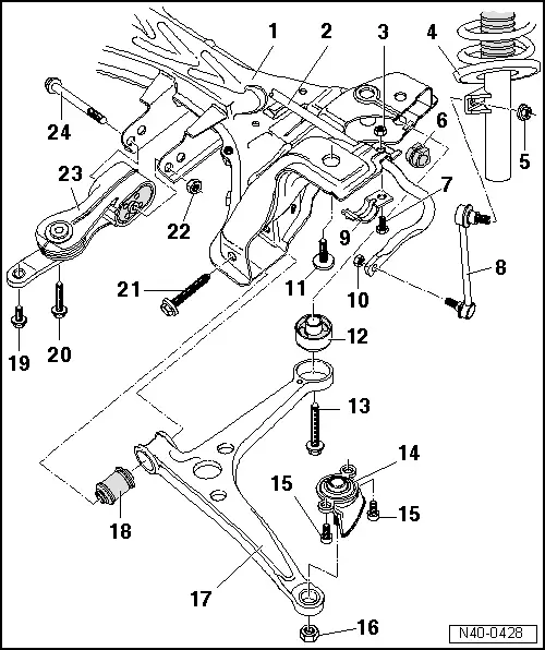
| 1 - | Strut |
| After assembly, the position of the steering wheel must be checked during a test drive. |
| If the steering wheel is misaligned, the convergence of the front axle must be checked and, if necessary, adjusted! |
| 2 - | Stabilizer bar |
| q | Removing and fitting → Chapter |
| 3 - | Hexagonal nut, 55 Nm |
| 4 - | Suspension strut |
| q | Allocation → Electronic parts catalogue“ETKA” |
| q | Repairing → Chapter |
| 5 - | Self-locking nut, 100 Nm |
| q | Always replace |
| 6 - | Rubber bush |
| 7 - | Hexagonal bolt |
| 8 - | Coupling rod |
| 9 - | Clamp |
| 10 - | Nut, 100 Nm |
| q | Allocation → Electronic parts catalogue“ETKA” |
| 11 - | Hexagonal bolt M14 x 1.5 x 65 |
| q | 150 Nm, and turn a further 90° |
| q | Replace after each removal |
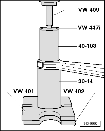
| 12 - | Rear socket for the swinging arm |
| q | Releasing → Fig. |
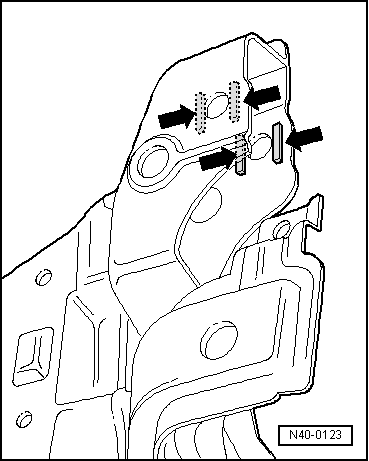
| q | Assembly position → Fig. |
| q | Fitting → Fig. |
| 13 - | Hexagonal bolt M14 x 1.5 x 95 |
| q | 150 Nm, and turn a further 90° |
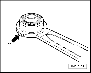
| q | Before tightening, check that the rear bonded rubber bush is correctly positioned on the strut → Fig. |
| q | Replace after each removal |
| 14 - | Ball joint |
| q | Removing and fitting → Chapter |
| 15 - | Allen screw, 55 Nm |
| 16 - | Self locking nut |
| q | 30 Nm, and turn a further 90° |
| q | Replace after each removal |
| q | When tightening, immobilize with Allen key e/c 7 |
| 17 - | Swinging arm |
| q | Assembly position on the strut → Fig. |
| q | Removing and fitting → Chapter |
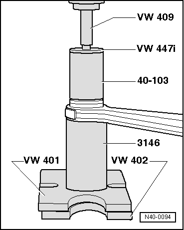
| 18 - | Front socket for the swinging arm |
| q | Releasing → Fig. |
| q | Fitting → Fig. |
| 19 - | Hexagonal bolt |
| q | 60 Nm, and turn a further 90° |
| q | Replace after each removal |
| 20 - | Hexagonal bolt |
| q | 60 Nm, and turn a further 90° |
| q | Replace after each removal |
| 21 - | Hexagonal bolt M14 x 1.5 x 90 |
| q | 90 Nm, and turn a further 90° |
| q | Replace after each removal |
| 22 - | Hexagonal nut |
| q | 90 Nm, and turn a further 90° |
| q | Replace after each removal |
| 23 - | Pendulum support |
| 24 - | Hexagonal bolt |
|
|
|
|
|
|
|
|
|
|