seat Workshop Repair Guides

SEAT Workshop Service and Repair Manuals

To replace the bonded rubber bearing of the strut replace > < Sub-frame
Removing and installing subframe
Consult the equivalence table for tools and equipment according to applicability between Seat / VW / Audi / Skoda → Chapter.
   
Special tools and workshop equipment required
t  Support bracket -10 - 222 A-
t  Rack -10 - 222 A /1-
t  Locating pins -3393-
t  Torque wrench -V.A.G 1331-, see equivalent → Anchor.
t  Torque wrench -V.A.G 1332-, see equivalent → Anchor.
t  Engine and gearbox lifter -V.A.G 1383 A-, see equivalency → Anchor

Removal:
   
–  Place the support bracket -10-222 A- with the adapters -10-222/3- on the screw joint edges of the mudguard.
–  Remove wheels.
  A34-10016
–  Loosen the quick locks-1 … 3- and remove the front and rear noise damping.
  A10-1320
–  Thread off the bracket of the noise damping -arrow-.
  A10-0968
–  Before loosening the subframe, use locating pins - 3393- to check whether holes -1- and -2- are aligned.
If this is not the case, wheel alignment has to be performed after installing the subframe.
–  Remove anti-roll bar → Chapter.
  A40-0125
–  Thread off the fastening nut -1- of the support on the engine.
–  On vehicles with headlight range control, detach coupling rod for vehicle level sender from track control link → Chapter.
  A40-0397
In order not to damage the joints of the top axle link if deflection of the spring on stretching is too high, the wheel bearing housing should be supported by a device e.g. the setting fixture -T20209 -.
  E40-10231
–  Unscrew bolt -3- from track control link.
–  Position engine and gearbox jack -V.A.G 1383 A- with suitable wooden block under subframe and press subframe upwards lightly.
–  Thread off the screwed joint of the bottom steering link to the sub-frame → Item.
  Note
To prevent the outboard joints on the track control links and guide links from being bent too far, secure the links to the car body with a piece of wire or similar.
  A40-0389
–  Unhook lower mount -arrow- on starter line from right engine console.
  A40-0398
–  First remove the hexagon bolts -4- and then the bolts -3-.
–  Remove the hexagon bolts -1- and loosen the bolts -2- enough so that the subframe can be removed.
Installation
Installation is carried out in the reverse sequence; note the following:
Fasten sub-frame with aid of check gauge -3393- to body before tightening.
  A40-0391
–  Hole -1-, hole -2- in subframe and hole -3- in aluminium bracket must be in alignment on both sides.
  Note
t  This locating method avoids the need for a subsequent wheel alignment check, provided that:
t  Only the subframe has been removed and installed.
t  The holes -1- and -2- were matched before the repairs.
–  Protect holes in body for mounting check gauges -3393- against corrosion.
  A40-0126
–  Place the sub-frame at its assembly location and insert the hexagon bolts -1...4- in their locations.
  A40-0391
–  Screw on nut -1-.
–  Insert track control links and guide links in subframe.
–  Thread off the screwed joint of the bottom steering link to the sub-frame → Item.
  A40-0397
–  Screw in bolts -3- of the track control link.
  A40-0389
–  Hook lower mount -arrow- on starter line into right engine console.
Tightening sequence
  Note
t  The threads of the bodywork can be made operational with the threaded insert (Heli-Coil) according to DIN 8140. The threaded insert must have the same length as the threads of the bodywork.
t  Bonded rubber bushes can only be turned to a limited extent. The mountings of the suspension links must therefore only be tightened when the suspension is in the unladen position → Chapter.
  A40-0398
–  Tighten the hexagon bolts -1 and 3- to 110 Nm and re-tighten to 90°.
–  Tighten the hexagon bolts -2- to 65 Nm.
–  Tighten the hexagon bolts -4- to 75 Nm.
  A40-0391
–  Tighten the nuts -1- of the engine bearing to 23 Nm.
  A40-0397
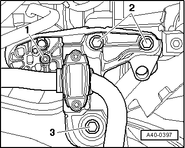
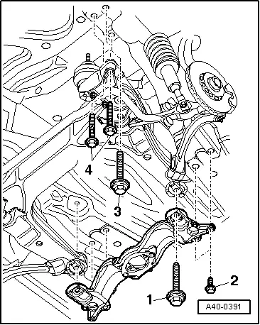
–  Tighten the hexagon bolts -3- of the track control link to 70 Nm and continue for 180°.
–  Tighten the hexagon bolts → Item of the track control link to 70 Nm and continue for 180°.
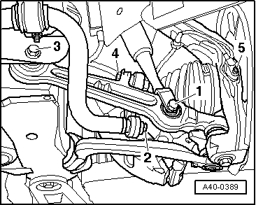
–  Install the stabiliser bar and tighten the bolts with the appropriate torque → Chapter.
–  Mount the wheels and the tighten the wheel bolts → Running gear, axles, steering; Rep. gr. 44
  Note
t  
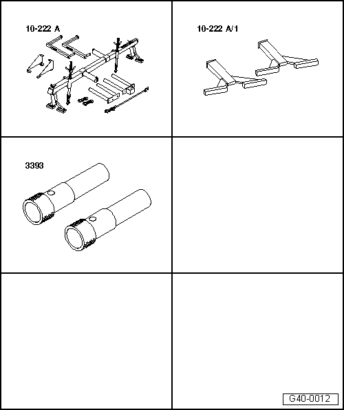
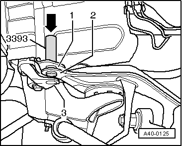
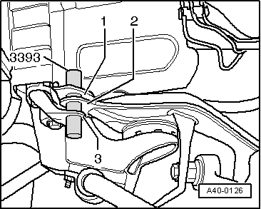
If attachment to the bodywork was made with the test mandrels -3393- before the assembly of the sub-frame (before final tightening of the bolts), the wheel axle alignment can be dispensed with.
t  If such a fixing has not been done, axle alignment is necessary.
–  If necessary, perform an → Chapteraxle alignment.
Setting of the running gear must be done with an alignment stand recommended by SEAT.
  A40-0389

To replace the bonded rubber bearing of the strut replace > < Sub-frame