
Leon Mk2
| Subframe: Assembly overview |
 Caution
|

| 1 - | Sub-frame |
| q | Securing → Chapter |
| q | Lowering → Chapter |
| q | Removing and installing without steering box → Chapter |
| q | Removing and installing with steering box → Chapter |
| q | Different versions available |
| q | Assignment → Electronic parts catalogue „ETKA“ |
| 2 - | Adapter |
| 3 - | Mounting bracket |
| q | Securing → Fig. |
| q | With bonded rubber bush |
| 4 - | Bolt. |
| q | M10 x 70 |
| q | 50 Nm and then turn 90° further |
| q | Always renew if removed |
| 5 - | Front left vehicle level sender -G78- |
| q | removing and installing → Chapter |
| q | Can be tested in guided fault finding using → Vehicle diagnostic tester |
| 6 - | Bolt. |
| q | 9 Nm |
| 7 - | Bolt. |
| q | M12 x 1.5 x 100: 70 Nm and then turn 180° further |
| q | Always renew if removed |
| 8 - | Wishbone |
| q | If damaged, also renew swivel joint |
| q | removing and installing → Chapter |
| q | Renew mounting → Chapter |
| q | Different versions of suspension links are possible (cast steel, sheet steel, aluminium). |
| q | Assignment → Electronic parts catalogue „ETKA“ |
 Note
Note| A mixed installation of suspension links of different types or made of different materials is not permissible. |
| 9 - | Nut |
| q | 9 Nm |
| 10 - | Bolt. |
| q | M12 x 1.5 x 90 |
| q | 70 Nm and then turn 180° further |
| q | Always renew if removed |
| 11 - | Bolt. |
| q | M14 x 1.5 x 70 |
| q | 100 Nm and then turn 90° further |
| q | Do not tighten until pendulum support is bolted to gearbox |
| q | Always renew if removed |
| 12 - | Bolt. |
| q | M10 x 75: 50 Nm and then turn 90° further |
| q | M12 x 1.5 x 85: 60 Nm and then turn 90° further |
| q | Always renew if removed |
| 13 - | Bolt. |
| q | M10 x 35: 50 Nm and then turn 90° further |
| q | M12 x 1.5 x 50: 60 Nm and then turn 90° further |
| q | Always renew if removed |
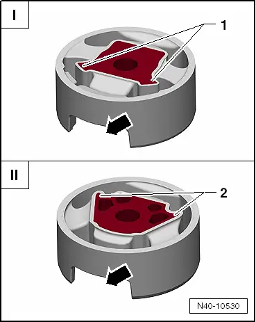
| 14 - | Lower bonded rubber bush for pendulum support |
| q | Pressing off and driving in → Chapter |
| q | Different versions → Fig. |
| 15 - | Pendulum support |
| q | Bolt to gearbox first, then to subframe |
| q | Different versions available |
| q | Assignment → Electronic parts catalogue „ETKA“ |
| 16 - | Upper bonder rubber bush for pendulum support |
| q | Pressing off and driving in → Chapter |
| q | Different versions → Fig. |
| 17 - | Bolt. |
| q | M12 x 1.5 x 110 |
| q | 70 Nm and then turn 180° further |
| q | Always renew if removed |
| q | Tighten only when the vehicle is in unladen weight position. → Chapter |
| 18 - | Bolt. |
| q | M12 x 1.5 x 100 |
| q | 70 Nm and then turn 180° further |
| q | Always renew if removed |
Note
|
|