seat Workshop Repair Guides

SEAT Workshop Service and Repair Manuals

Installing > < Removing and installing subframe
Removal:
Removal:
   
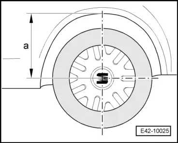
Before raising the vehicle, size-a- must be measured with the measuring tool -T20095 - and noted.
–  Raise the vehicle and remove the front wheels.
–  Remove the lower sound insulation → Bodywork, exterior installation work; Rep. gr. 50 .
  E42-10025
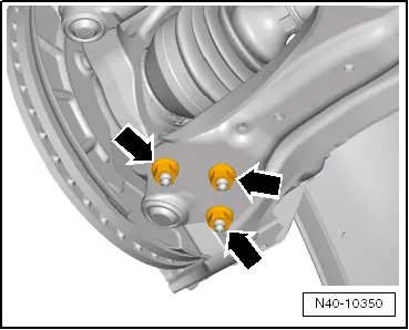
–  Unscrew the bolts -arrows- from the suspension ball joint.
  Note
During disassembly and assembly work, take care that the rubber bellow of the ball joint is not damaged. Where necessary, protect the rubber bellow of the ball joint against damaged.
–  Release the ball joint, along with the front suspension assembly, from the transverse swinging arm.
  N40-10350
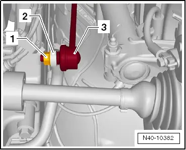
–  Unscrew the nut -1- from the link rod -3- on both sides of the vehicle.
–  Separate the link rods -3- from the stabiliser bar -2-.
–  Turn anti-roll bar upwards.
  N40-10382
–  Unscrew the pendulum support bolt from the gearbox.
Vehicle with exhaust pipe under the subframe
–  Remove the front section of the exhaust pipe: → Rep. gr.26.
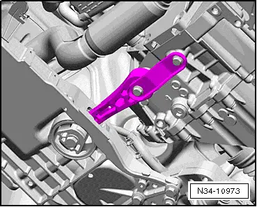
Vehicles with exhaust pipe above the subframe
  N34-10973
–  Pull retaining rings -arrows- for exhaust pipe from subframe. The number of retaining rings on the subframe may vary depending on equipment.
Continued for all vehicles
  A40-10431
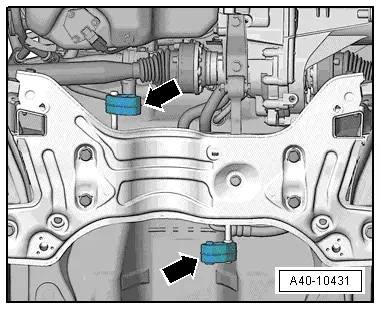
–  Remove the steering box from the subframe -arrows- and secure accordingly.
  N40-10330
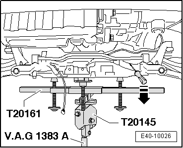
–  Prepare the motor driven lift -V.A.G 1383 A- with the base -T20145- and attachment tool - T20161- correctly under the subframe, in order to secure the attachment position on the bodywork, for subsequent fitting.
  Note
t  The terminals of the support tool -T20161- threaded shafts should insert into the swinging arm holes.
t  Clean the threads of the fastening bolts of the retention tool -T10096 -.
  E40-10026
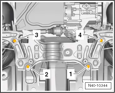
To fix position of subframe, locating pins -T10096- must be screwed one after the other into positions -1-, -2-, -3- and -4-.
Positions -3- and -4- must be fixed first.
  Note
The fastening bolts -T10096- can only be tightened to a maximum of 20 Nm, otherwise the thread of the bolt will be damaged.
  N40-10344
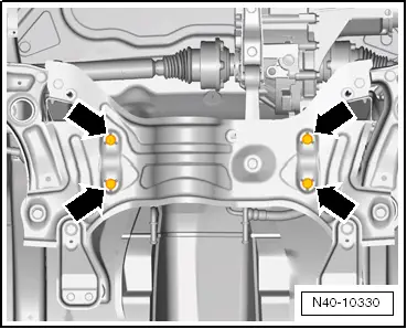
–  Replace securing bolts -2- along both sides of vehicle one after the other with locating pins -T10096- and tighten them to 20 Nm.
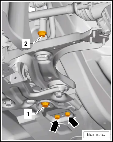
–  Unscrew bolts -arrows- for support.
–  Unscrew securing bolt -1- on one side of vehicle and remove support.
–  Insert locating pins -T10096- and tighten to 20 Nm.
–  The process of locating the subframe is complete when all 4 of the bolts have been replaced in turn with a locating pin from the locating pin set -T10096 -.
This way, the position of the strut is secured on the bodywork for subsequent fitting.
  N40-10347
–  Lower completely and carefully the subframe using the engine and gearbox jack -V.A.G 1383 A- with the base -T20145- and the counterhold -T20161 -.
–  Condition the subframe on a work bench.
  E40-10026

Installing > < Removing and installing subframe