seat Workshop Repair Guides

SEAT Workshop Service and Repair Manuals

Wheel bearing / wheel hub unit: Removing and installing > < Wheel bearing housing and wheel bearing / wheel hub nut: Assembly overview
Removing and installing wheel bearing housing
Consult the equivalence table for tools and equipment according to applicability between Seat / VW / Audi / Skoda → Chapter.
Special tools and workshop equipment required
   
t  Ball joint separator -T40010 -, see equivalency → Anchor
  W00-1088
t  Special tools -T40067-
t  Torque wrench -V.A.G 1331-, see equivalent → Anchor.
t  Torque wrench -V.A.G 1332-, see equivalent → Anchor.
Removal:
–  Remove bolt securing drive shaft (loosen only when vehicle is standing on wheels -danger of accident-) → Anchor.
–  Remove the line of the speed sensor for ABS/ESP from its support on the wheel bearing assembly.
  A40-10016
–  Thread off the screw -5- of the speed sensor for ABS/ESP.
–  Hook the speed sensor for ABS/ESP from the wheel bearing assembly.
–  Disassembly the brake disk → Brake system; Rep. gr.46.
  A40-0389
–  Remove bolts -arrows- and take off splash plate.
  A40-0390
–  Remove bolts -3- and -4-.
  Note
t  After repairs, check the wheel alignment → Chapter.
  A40-0473
t  Do not use any chisel or similar tool between the steering rod -1- and the washer -2- of the joint of the track rod to adjust the track rod. That would damage the washer.
t  To separate the track rod from the steering rod, use only a wooden head or rubber hammer to apply pressure or to impact the stud end of the track rod.
–  Pull out or press out track rod downwards.
–  Thread off the nut of the steering link until the threads of the joint close smoothly. If necessary, counter-hold the joint with a 4-mm internal socket (Allen) key.
  A40-0475
–  Pull out the joint of the steering link with the clamp extractor - T40010 - from its taper seat.
  Note
t  Do not damage the joint protection sleeve!
t  Make sure the two lever arms of the puller are parallel when maximum force is exerted.
–  On vehicles with headlight range control, detach coupling rod for vehicle level sender from track control link → Chapter.
–  Thread off the nut of the track control link until the threads of the joint close smoothly. If necessary, counter-hold the joint with a 4-mm internal socket (Allen) key.
  A40-0274
–  Pull out the joint of the track control link with the clamp extractor - T40010 - from its taper seat.
  Note
Make sure the two lever arms of the puller are parallel when maximum force is exerted.
  A40-0275
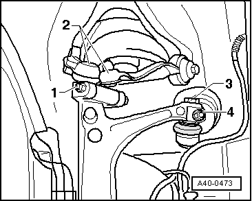
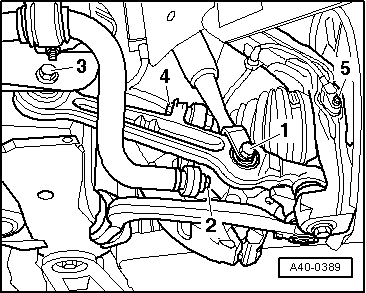
–  Loosen nut -1-, take out hexagon bolt and pull out both upper links -2- upwards.
Do not attempt to enlarge slots in wheel bearing housing using a chisel or similar.
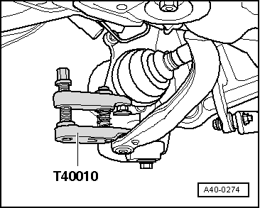
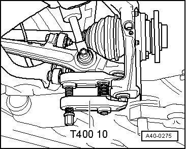
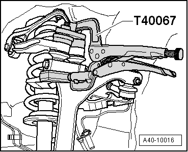
–  Rotate the wheel bearing assembly in the direction of the arrow so that it will not hamper the removal of the drive shaft pin from the wheel hub.
–  Fasten the drive shaft e.g. with wire, on the body.
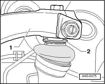
–  Unscrew the nut from the joint on the track control link.
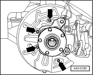
–  Take off wheel bearing housing.
Installation
Installation is carried out in the reverse sequence; note the following:
–  Fit wheel bearing housing.
–  Insert the joint on the outer side of the drive shaft in the wheel hub and tighten the new hexagon bolt by hand.
–  Insert the joint of the track control link and of the steering link in the wheel bearing assembly.
–  Thread on and tighten new self-locking nuts → Item; if necessary, counter-hold the joint with a 4 mm internal socket (Allen) key.
  A40-0473
–  Fit both joints of both upper links in wheel bearing housing and press down as far as possible by clamping with special tool -T40067 -.
  A40-10016
–  Install and tighten new bolt -1- and self-locking nut → Item.
  Note
  A40-0473
The track rod (the joint of the track rod) may be mounted in the steering rod -1- only by hand. Do not overload the washer -2- in any case.
–  Insert track rod.
  A40-0475
–  Fit and tighten new self-locking nut -4- → Item.
–  Tighten the hexagonal bolt -3- → Item.
–  Install ABS speed sensor. → Brake system; Rep. Gr. 45
–  On vehicles with headlight range control, fit coupling rod for vehicle level sender on track control link → Chapter.
  A40-0473
–  Fit splash plate and tighten bolts → Item.
–  Install brake disc and brake caliper → Brake system; Rep. Gr. 46
–  Mount the wheels and the tighten the wheel bolts → Running gear, axles, steering; Rep. gr.44
–  Tighten hexagon head screw on propeller shaft to specified tightening torque (tighten only on vehicles standing on wheels - accident hazard). → Chapter.
–  Wheel alignment → Chapter
Setting of the running gear must be done with an alignment stand recommended by SEAT.
  A40-0390

Wheel bearing / wheel hub unit: Removing and installing > < Wheel bearing housing and wheel bearing / wheel hub nut: Assembly overview