seat Workshop Repair Guides

SEAT Workshop Service and Repair Manuals

Checking the interior constant velocity joint > < Rear driveshaft: removing and fitting|Fitting
Rear driveshaft: repairing
   
Rear driveshaft: repairing
Special tools and workshop equipment required
t  Pressure plate -VW 401-
t  Pressure plate -VW 402-
t  Terminal crimper -VW 408 A-
t  Support sleeves -VW 522-
t  Tensor -40 - 204 A-
t  Pliers -V.A.G 1682-

   
t  Torque wrench -V.A.G 1331-
  W00-0427
t  Torque wrench -V.A.G 1332-
Filling the inner constant velocity joint with grease:
Total amount of grease: 90 g of lubricating grease -G 000 603-
t  Insert approx. 45 g of grease on both sides of the seal.
t  If the dust guard is replaced, the seal may need to be re-greased.
  W00-0428
1 - Hexagonal bolt
q   150 Nm, and turn a further 90°
q   Replace after each removal
2 - Driveshaft with outer joint
q   The outer joint cannot be removed from the driveshaft
q   The outer joint cannot be repaired, and the dust guard cannot be replaced
q   Replace if damaged
3 - Bolt with internal splined head
q   First tighten diagonally to 10 Nm
q   Tighten completely to 40 Nm
4 - Additional plate
5 - Tightening clip
q   Replace
q   Tighten → Fig.
6 - Dust guard of the inner constant velocity joint
q   Ensure that there is no damage or cracks from friction
q   Take out using a punch.
7 - Inner constant velocity joint
q   Only replace entirely
q   Releasing → Fig.
q   Fitting → Fig.
q   Checking → Chapter
q   Grease → 
8 - Seal
q   Replace, remove the protection layer and attach it to the joint.
9 - Circlip

   
Removing the interior constant velocity joint
  Note
t  Separate the dust guard with a punch
t  Secure the ball hub.
  V40-0859
Fit the inner constant velocity joint
–  Insert the constant velocity joint up to the limit.
–  Insert the securing ring.
  Note
The bevel of the interior diameter of the ball hub (cogged) must face the support collar of the driveshaft.
  V40-0860
Tighten the clamp of the inner joint
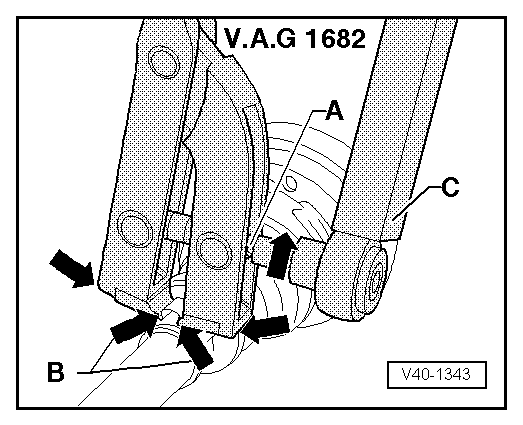
–  To do so, position the pliers -V.A.G 1682- as shown in the figure. Ensure that the edges of the tool fit into the corners -arrows B- of the clamp.
–  Tense the clamp by turning the spindle using the torque wrench taking special care not to incline the pliers during the operation.
  Note
t  Given the firmness of the material (in comparison with the rubber) of the union dust guard, a stainless steel clamp is required, this can only be tightened using the pliers -V.A.G 1682-.
t  Tightening torque: 20 Nm
t  
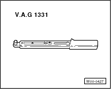
Use a torque wrench-C- with a range between 5 and 50 Nm (e.g. -V.A.G 1331-).
t  Check that the spindle thread -A- of the pliers can be tightened without forcing. Apply grease -MOS 2-, if necessary.
t  If the thread does not turn easily (due to dirt, for example), it will not be possible to tighten the clamp sufficiently when applying the specified torque.
  V40-1343

Checking the interior constant velocity joint > < Rear driveshaft: removing and fitting|Fitting