seat Workshop Repair Guides

SEAT Workshop Service and Repair Manuals

Vehicle level sender for vehicles with automatic headlight range control > < Removing and installing subframe
To replace the bonded rubber bearing of the strut replace
Consult the equivalence table for tools and equipment according to applicability between Seat / VW / Audi / Skoda → Chapter.
Special tools and workshop equipment required
   
t  Engine and gearbox lifter -V.A.G 1383 A-, see equivalency → Anchor
t  Torque wrench -V.A.G 1331-, see equivalent → Anchor.
t  Torque wrench -V.A.G 1332-, see equivalent → Anchor.
  W00-0120
t  Pedal pump with high-pressure hose -V.A.G 1389 A/1-
If there is a hand pump -V.A.G 1389/1- available in the dealership it can be converted to a foot-operated pump.
Use the retrofit kit -V.A.G 1389/4- for it.
Special tools and workshop equipment required
  W00-0681
t  Hydraulic wheel bearing tool -V.A.G 1459 B-
t  Hollow piston cylinder HKZ-15 -mit Druckstück E-0-204-T hydraulisch-
t  Pull bolt -E-0-217+218-
t  Special nut -E-8-214-
t  pressure tool -E-5-
t  pressure tool -T40033/1-
t  Support ring -T40033/2-
t  Tube -T40033/3-
t  Mounting -T40033/4-
t  pressure tool -T40033/5-
t  Mounting -T40033/6-
t  Spindles -T40034-
t  Nut -T40034/1-
t  Nut -T40034/2-
  Note
t  The subframe bushes are hydro-bushes, not conventional bonded rubber bushes → Spare parts catalogue
t  The bushes can only be removed and installed with the subframe lowered.
t  Mark position of bushes in relation to subframe before removing.
Remove front and rear rubber metal bearings.
–  Remove wheels.
–  Install coil springs (left and right) → Chapter.
  W00-0676
–  Remove the rear left or right underbody trim only if the front bonded rubber bushes need to be replaced.
1  - Underbody trim (left-side)
Only for the rear bonded rubber bushes
–  Remove anti-roll bar → Chapter.
Continued: front and rear bonded rubber bushes
  A42-0331
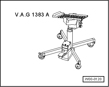
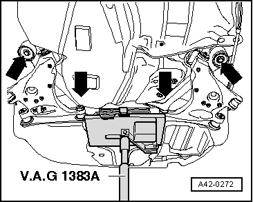
–  Position engine and gearbox lifter -V.A.G 1383 A- on subframe with suitable wooden insert.
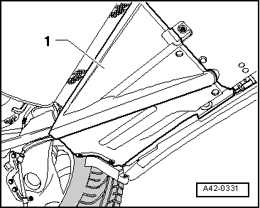
–  Tension tensioning belt -T10038- around subframe.
  Note
t  If a front bonded rubber bush needs to be replaced, loosen only the front bolts of the subframe.
t  If a rear bonded rubber bush needs to be replaced, loosen only the rear bolts of the subframe.
t  If a further subframe bolt is loosened (front or rear), wheel alignment must be performed following installation.
–  Loosen the front or rear bolts behind the subframe.
–  Carefully lower the subframe to about 5 cm.
–  Pull out only such bolts from the subframe, where the bonded rubber bush needs to be replaced.
  A42-0272
–  Using felt pen or similar, mark position of bonded rubber bearing -1- in relation to subframe -2- (illustration shows subframe of a front-wheel drive vehicle).
Arrow A: Direction of travel
Arrows B and C: Mark
  A42-0332
–  Apply special tools as shown in illustration.
1  - Nut -T40034/1- or -T40034/2-
2  - pressure tool -T40033/1-
3  - Support ring -T40033/2-
4  - Tube -T40033/3-
5  - Mounting -T40033/4-
6  - Hollow piston cylinder -HKZ-15-
7  - pressure tool -E-5-
8  - Special nut -E-8-214-
9  - Spindles -T40034-
10 - Subframe
–  Pretension the specialist tools.
–  Pull out bonded rubber bush by actuating pump.
  Note
A readjustment is necessary while removing the bonded rubber bush with special tool hydraulic wheel bearing tool - V.A.G 1459 B- .
Fitting front / rear bonded rubber bush.
The front hydro-bushes are different from the rear ones. Make sure to place them in the correct place while inserting. → Spare parts catalogue
The bonded rubber bush must be mounted in a certain position. Refer to the marking on the subframe.
  A42-0333
–  Mount the special tools and the bonded rubber bush on the subframe as shown in the illustration.
Ensure correct position when attaching support -T40033/6-.
1 - Nut -T40034/1- or - T40034/2-
2 -  Mounting -T40033/6-
3 -  Bonded rubber bush
4 -  pressure tool -T40033/5-
5 -  Hollow piston cylinder -HKZ-15-
6 -  pressure tool -E-5-
7  - Special nut -E-8-214-
8  - Spindles -T40034-
9 - Subframe
–  Pretension the specialty tools with the bonded rubber bush.
–  Apply the lubricating grease G 294 421 A1 diluted with water at a ratio of 1:100 on the entire surface of the bonded rubber bush.
  A42-0334
–  Make sure that the ends of the rubber bulges of the bonded rubber bush -1- correspond with the markings -arrows B and C-on the subframe -2-.
-Arrow A- direction of travel
–  Fully fit the bonded rubber bush by means of pump action.
  Note
t  A readjustment is necessary while installing the bonded rubber bush with special tool -V.A.G 1459 B-hydraulic wheel bearing tool.
t  Take care not to bend the rubber bush while inserting. Otherwise the outer ring can be damaged.
–  Lift subframe with engine and gearbox jack -V.A.G 1383 A-.
–  Insert new flat washers and screw in new screws for the subframe and tighten, → Item and → Item
Only rear bonded rubber bush
–  Install anti-roll bar → Chapter.
Continued: front and rear bonded rubber bushes
–  Install underbody trim (left and right).
–  Install coil springs (left and right) → Chapter.
–  Mount the wheels and the tighten the wheel bolts → Running gear, axles, steering; Rep. gr. 44
–  Check wheels if more than 2 bolts have been loosened from the subframe → Chapter.
Setting of the running gear must be done with an alignment stand recommended by SEAT.
  A42-0332

Vehicle level sender for vehicles with automatic headlight range control > < Removing and installing subframe