
Leon Mk2
| Assembly overview of rear axle body, syncro |
| The parts which are not represented, e.g. the springs, rubber bushes, etc., are described from page → Chapter onwards |
 Note
Note| t | No welding or straightening work may be carried out on wheel guiding parts. |
| t | Always replace self-locking nuts following their removal. |
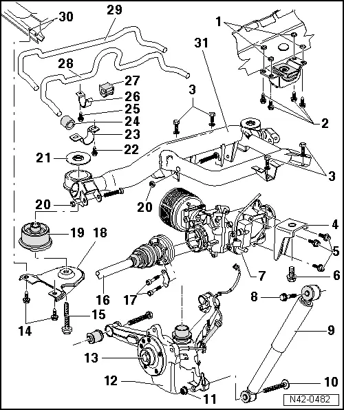
| 1 - | Screw thread on the cross member |
| If the thread of the nut welded onto the cross member is damaged, it may be repaired by using a Heli-Coil thread insert. |
| Repairing the thread on the cross member → Chapter |
| This repair can only be carried out if the support bracket is fastened with bolts → Item M10 x 30. |
| 2 - | Hexagonal bolt |
| q | Allocation → Electronic parts catalogue“ETKA” |
| q | M10 x 25; 65 Nm |
| q | M10 x 30; 50 Nm + 90° |
| q | Replace after each removal |
| 3 - | Hexagonal bolt, 30 Nm + 90° |
| q | Replace after each removal |
| 4 - | Support bracket |
| 5 - | Bolt with internal grooved head, 30 Nm + 90° |
| q | Replace after each removal |
| q | Use an inner splined socket 14 (standard) |
| 6 - | Hexagonal bolt, 260 Nm |
| q | Replace after each removal |
| 7 - | Final drive |
| q | Removing and fitting → Repair Group 39; Rear final drive: removing and fitting |
| 8 - | Hexagonal bolt, 110 Nm |
| q | Replace after each removal |
| 9 - | Pressurized gas shock absorber |
| q | Removing and fitting → Chapter |
| q | Allocation → Electronic parts catalogue“ETKA” |
| 10 - | Hexagonal bolt |
| q | Replace after each removal |
| 11 - | Nut, 130 Nm |
| q | Replace after each removal |
| 12 - | Swinging arm |
| 13 - | Wheel bearing assembly |
| q | Repairing → Chapter |
| 14 - | Hexagonal bolt, 100 Nm |
| 15 - | Hexagonal bolt, 170 Nm |
| q | Replace after each removal |
| 16 - | Driveshaft |
| q | Removing and fitting → Chapter |
| 17 - | Bolt with internal splined head |
| q | Tightening torque → Item |
| 18 - | Brace |
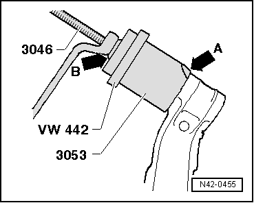
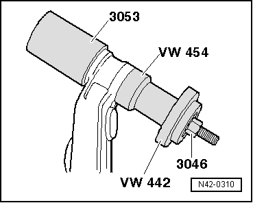
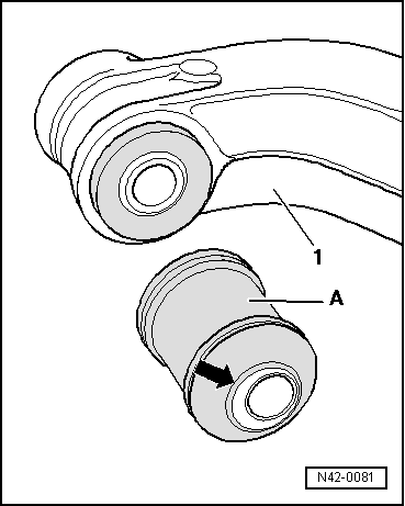
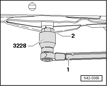
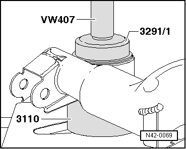
| 19 - | Bonded rubber bush |
| q | Releasing → Fig. |
| q | Mark the assembly position → Fig. |
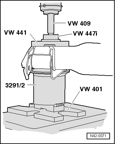
| q | Fitting → Fig. |
| 20 - | Nut, 170 Nm |
| 21 - | Lower base |
| 22 - | Hexagonal bolt, 30 Nm |
| 23 - | Clamp |
| 24 - | Rubber bush |
| 25 - | Hexagonal bolt, 30 Nm |
| 26 - | Clamp |
| 27 - | Grooved rubber bush |
| 28 - | Stabilizer bar |
| q | For vehicles up to 03.00 |
| 29 - | Stabilizer bar |
| q | For vehicles from 04.00 onwards |
| 30 - | Screw thread on longitudinal member |
| If the thread is damaged → Chapter |
| 31 - | Axle body |
| q | Align the axle body in relation to the vehicle → Chapter |
Note
|
|
|
|
| Assembly position | Adjustment |
| Upward eccentricity → Note | Negative adjustment of camber |
| Downward eccentricity → Note | Positive adjustment of camber |
| Forward eccentricity → Note | Positive adjustment of toe |
| Backward eccentricity → Note | Negative adjustment of toe |
|
|
|
|
|
|

|
|
|