| Component | Tightening torque |
Upper transverse link to wheel bearing housing| t
| Tighten threaded connections only when vehicle is in the normal running position |
| 130 Nm and then turn 90° further |
Wheel bearing housing to lower suspension link| t
| Tighten threaded connections only when vehicle is in the normal running position |
| 90 Nm and then turn 90° further |
Wheel bearing housing to track rod| t
| Tighten threaded connections only when vehicle is in the normal running position |
| 130 Nm and then turn 90° further |
| Trailing arm to wheel bearing housing | 90 Nm and then turn 45° further |
| Coupling rod to wheel bearing housing | 45 Nm |
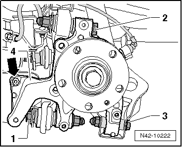
| Splash plate to wheel bearing housing | 12 Nm |
| ABS speed sensor to wheel bearing housing | 8 Nm |
| Shock absorber to wheel bearing housing | 180 Nm |
| Brake disc to wheel bearing housing | 4 Nm |
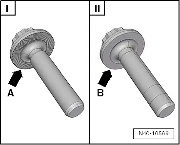
| Drive shaft to wheel hub „hexagon bolt“ | 180 Nm and then turn 180° further |
| Drive shaft to wheel hub „twelve-point head bolt with ribbing“ | 70 Nm + 90° |
| Drive shaft to wheel hub „twelve-point head bolt without ribbing“ | 200 Nm + 180° |

 Note
Note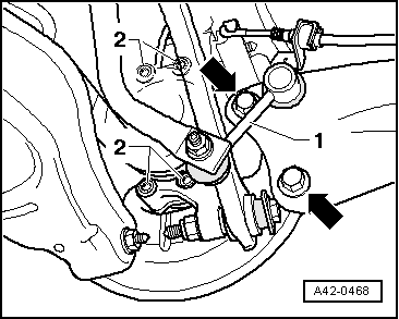
 Caution