
Leon Mk2
|
|
|
|
|
|
|
|
|
|
|
|
|
 Note
Note
|
|
| Specified torques |
| Bolt | Specified torque | ||||
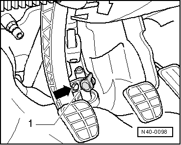
| Universal joint shaft to steering box | 25 Nm | ||||
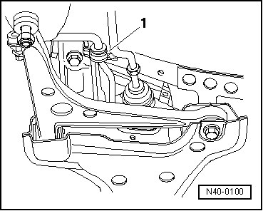
| Coupling rod to anti-roll bar | 100 Nm | ||||
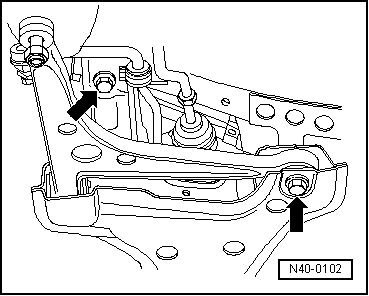
| Anti-roll bar to subframe | 55 Nm | ||||
Subframe to body
| 150 Nm + 90° further | ||||
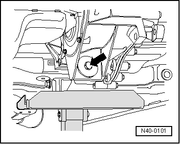
Pendulum support to gearbox
| 100 Nm | ||||
| Wheel bolts to wheel hub | → Chapter |