
Leon Mk2
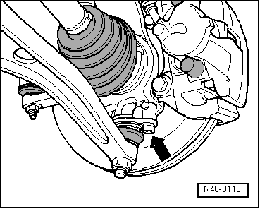
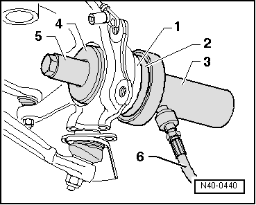
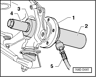
| Pressing front wheel bearing out and in with wheel bearing housing installed |

| Special tools and workshop equipment required |
| t | Torque wrench -V.A.G 1332- |
| t | Engine and gearbox jack -V.A.G 1383 A- with universal gearbox support -V.A.G 1359/2- |
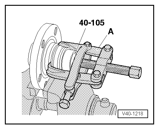
| t | Thrust piece -VAS 6016- |
| t | -3-Puller -Kukko 204/2- |
|
|
|
|
|
|
|
|
|
|
 Note
Note
|
|
|
|
|
|
|
|
|
|
|
|
| Specified torques |
| Bolt | Specified torque | ||
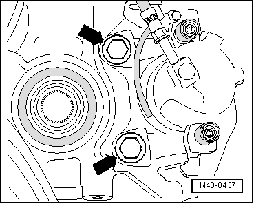
| Swivel joint to wheel bearing housing | 55 Nm | ||
Drive shaft to hub
| 150 Nm + 90° further | ||
| Brake carrier to wheel bearing housing | → Rep. Gr.46 | ||
| Wheel bolts to wheel hub | → Chapter |