| Removing and installing the hydraulic control unit - LHD version |
| The removal and installation of the relevant hydraulic control unit is described according to the example of the ABS system BOSCH 5.7. Removal and installation is similar for the ABS/EDL/TCS or ABS/EDL/TCS/ESP BOSCH 5.7. |

WARNING | t
| Make absolutely sure that no brake fluid gets into the plug connector housing of the hydraulic control unit. This may result in the corrosion of the contacts and to system failure. |
| t
| Carefully clean out the plug connector housing with compressed air if it gets dirty. |
| t
| Do not bend the brake lines around the hydraulic control unit. |
|
| Special tools and workshop equipment required |
| t
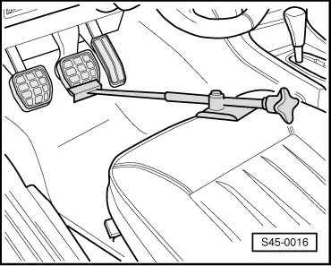
| Brake pedal arrester, e.g. -V.A.G 1238 B- or brake pedal load -V.A.G 1869/2 - |
| t
| Vehicle system tester -V.A.G 1552- or vehicle diagnosis, measurement and information system -VAS 505x- |
| t
| Brake filling and bleeding device, e. g. -VAS 5234- |
| t
| Bleeding bottle (commercially available) |
| t
| Repair kit SP-No. 1H0 698 311 A |

Note | Before disconnecting the battery determine the code of radio sets fitted with anti-theft coding. |
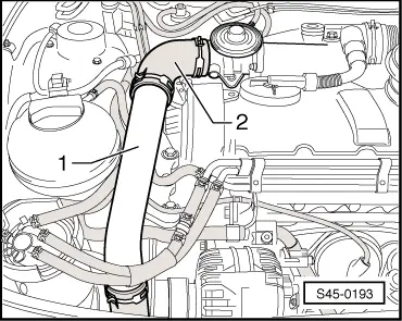
| Vehicles with TDI PD Turbocharger engines |
|
|
|