skoda Workshop Repair Guides

Skoda Workshop Service and Repair Manuals

Removing and installing brake pressure sender 1G201 - vehicles with ABS/EDL/TCS/ESP BOSCH 5.7 > < Removing and installing the hydraulic control unit - RHD version
Repairing the hydraulic control unit ABS or ABS/EDL/TCS BOSCH 5.7
The hydraulic control units ABS and ABS/EDL/TCS BOSCH 5.7 must be repaired, while the hydraulic control units ABS/EDL/TCS/ESP BOSCH 5.7 must not be disassembled. It must be replaced in case of repairs. For ABS/EDL/TCS/ESP only the brake pressure sender 1 -G201- must be replaced → Chapter.
  Note
t  Inspecting and repairs of the hydraulic control unit must only be performed by skilled personnel in approved automobile workshops (Bosch service centres or contract dealers of the vehicle manufacturer).
t  Observe the notes in the manufacturer's instructions for the replacement of hydraulic control units.
Special tools and workshop equipment required
t  Caliper gauge (commercially available)
  Note
t  The sealing surface on the hydraulic control unit must be clean and undamaged. It must never be reworked, (e.g. with files, scrapers etc.). If necessary replace the hydraulic unit.
t  The gasket on the control unit must not be removed, it cannot be replaced.
t  The screws (inner Torx T20) of the hydraulic unit/control unit must be replaced after each removal. Use the screws included in the parts kit. Tightening must occur in the prescribed sequence and in steps.
t  If the control unit is being replaced tentatively tighten the fixing screws only slightly Only tighten the screws to the specified tightening torque once the control unit is correctly positioned on the hydraulic control unit.
   
t  Maximum 5 tightening procedures (hydraulic unit) may be carried out throughout the entire life of the hydraulic control unit. Pay attention to the colour markings (approx. 3 mm wide red lines) on the hydraulic control unit. Replace the complete hydraulic control unit if more than 5 tightening procedures have been performed (-arrow- area for colour markings).
t  The threads in the hydraulic unit for securing the control unit must not be rethreaded. If the thread is damaged (screws are hard to tighten by hand or they cannot be tightened to the prescribed torque) replace the hydraulic control unit.
t  Blowing out of the control unit or the hydraulic unit with compressed air to secure an oily or aqueous film on and between the valve domes or the solenoid coils is not permissible! Only use moisture-free and oil-free compressed air, e.g. from a spray. Cleaning with hydrocarbon solvents is not allowed.
t  If the hydraulic control unit is open protect the valve domes, solenoid coils, contact springs against damage and soiling.
t  If the hydraulic control unit is open it is not permissible to apply a voltage to the contact springs of the hydraulic pump. Risk of contact arcing.
t  Repair is only possible with the hydraulic control unit removed.
t  Disassembly and assembly of the hydraulic control unit is described on an ABS unit BOSCH 5.7. The procedure for the ABS/EDL/TCS unit BOSCH 5.7 is identical. The ABS/EDL/TCS/ESP unit BOSCH 5.7 must not be disassembled. It must be replaced in case of repairs. Only the brake pressure sender 1 -G201- must be replaced → Chapter.
–  Remove hydraulic control unit with bracket → Chapter
Disassembling the hydraulic control unit
  S45-0111
Hydraulic unit for ABS -N55 - with return flow pump for ABS - V39- (-a-):
t  Hydraulic control unit: The valve block includes the control valves and the contact springs of the hydraulic pump.
t  Do not separate the return flow pump for ABS -V39- from the hydraulic unit for ABS -N55-.
ABS control unit -J104- (-b-):
t  Contact assignment → Chapter
  Note
The hydraulic control unit ABS/EDL/TCS/ESP BOSCH 5.7 must not be disassembled. It must be replaced as a complete unit in the case of repairs. Only the brake pressure sender 1 -G201- must be replaced → Chapter.
  S45-0068
–  Release inner Torx screws T20 Pos. -1 through to 6-.
  S45-0071
When tightening the control unit -b- of the hydraulic unit -a- make sure the valve domes -1- are not tilted along with the solenoid coils -4-.
3 - Silicone seal
–  Cover the solenoid coils of the control unit.
–  Protect the valve domes and contact springs -2- of the return flow pump for ABS -V39- against damage and soiling. Do not use fluffing cloths or a transport protection of an already installed spare part hydraulic pump. This is a requirement for possible guarantee claims.
Assembling the hydraulic control unit
vehicles with ABS/EDL/TCS BOSCH 5.7
  S45-0070
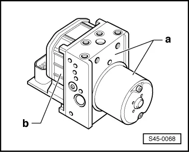
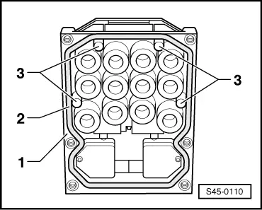
If new or removed control units -1- are installed again, inspect the heat conduction posts -3-.
–  Inspect the end faces of the heat conduction posts for good heat conduction properties. The faces must not exhibit any deposit, e.g. oxidation.
–  Check projection of the posts using a gauge.
   Dimension must be of 0.8...1.0 mm between the top side of the heat conduction posts and the seal -2-.
–  Press the end face of the heat conduction posts with your thumb, they must give.
If faults are found during one of the 3 test steps, the control unit must be replaced.
Continued for all vehicles
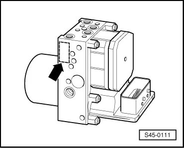
–  Inspect the sealing surface on the hydraulic unit for soiling, if necessary clean with white spirits and a non-fluffing paper or linen cloth.
–  If an oily or aqueous film appears on the surface of the hydraulic unit, clean with white spirits and a non-fluffing paper or linen cloth.
–  If there is a considerable oily and aqueous film between the valves use moisture-free and oil-free compressed air to blow it out.
–  If damage is noticed on the hydraulic unit (e.g. scoring or scratching etc.) near the seal, replace the hydraulic unit.
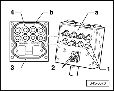
–  Inspect the contact springs of the hydraulic pump for burning points and oxidation. Reworking or cleaning is not possible, replace the hydraulic unit.
  Note
t  Before fitting the control unit to the hydraulic unit make sure the seal protrudes by min. 0.1 mm from the control unit housing.
t  When assembling the control unit and the hydraulic unit make sure the valve domes of the hydraulic unit do not tilt along with the solenoid coils of the control unit.
–  Place the control unit on the hydraulic unit and guide the solenoid coils over the valves by exerting a slight pressure. While doing so center the control unit relatively to the hydraulic unit. The edge of the control unit must engage in the groove of the hydraulic unit.
–  Press by hand on the control unit until it fixes in place with the two centre screws.
  Note
t  
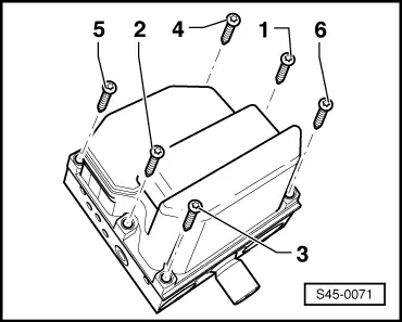
Screw on the hydraulic unit and the control unit in the prescribed sequence and in steps. Tightness will not be guaranteed if this is not observed.
t  Only use new inner Torx screws from the parts kit.
t  When screwing together make sure the left and right gap between the control unit and the hydraulic unit is always the same.
  S45-0110
–  First screw in the inner Torx screws and tighten them by hand in the alternating sequence 1 - 2, 3 - 4, 5 - 6.
–  Tighten all inner Torx screws in the alternating sequence 1 - 2, 3 - 4, 5 - 6 to the prescribed tightening torque.
  S45-0071
–  Indicate each fitting of the hydraulic unit with the control unit in the area -arrow- with a permanent mark approx. 3 mm wide. Colour: red.
   For this use e.g. lead seal enamel.
–  Install hydraulic control unit with bracket → Chapter.
  S45-0111
Tightening torque:
Control unit to hydraulic unit
t  Use new screws!
3 Nm


Removing and installing brake pressure sender 1G201 - vehicles with ABS/EDL/TCS/ESP BOSCH 5.7 > < Removing and installing the hydraulic control unit - RHD version