skoda Workshop Repair Guides

Skoda Workshop Service and Repair Manuals

Removing and installing bracket for the hydraulic control unit > < Removing and installing the hydraulic control unit - LHD version
Removing and installing the hydraulic control unit - RHD version
  WARNING
t  
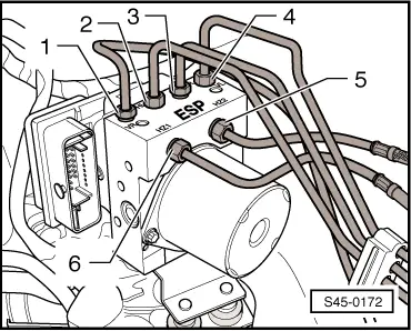
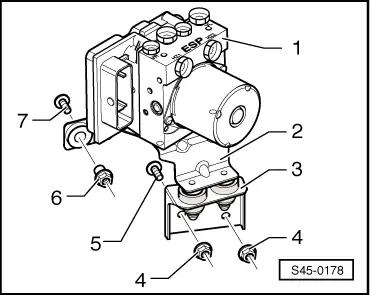
Make sure that no brake fluid gets into the plug connector housing of the hydraulic control unit. This may result in the corrosion of the contacts and to system failure.
t  Carefully clean out the plug connector housing with compressed air if it gets dirty.
t  Do not bend the brake lines around the hydraulic control unit.
Special tools and workshop equipment required
t  
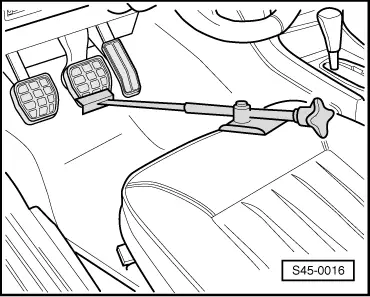
Brake pedal arrester, e.g. -V.A.G 1238 B- or brake pedal load -V.A.G 1869/2 -
t  Vehicle system tester -V.A.G 1552- or vehicle diagnosis, measurement and information system -VAS 505x-
t  Brake filling and bleeding device, e. g. -VAS 5234-
t  Bleeding bottle (commercially available)
t  Repair kit SP-No. 1H0 698 311 A
t  Brake fluid → Chapter
Removing:
  Note
Before disconnecting the battery determine the code of radio sets fitted with anti-theft coding.
–  Disconnect battery → Electrical System; Rep. gr.27.
–  Remove engine cover → Engine, Mechanics; Rep. gr.10.
–  Remove air filter → Engine, Fuel Injection; Rep. gr.24, or → Engine, Fuel Injection; Rep. gr.23.
   
–  Actuate brake pedal and arrest with brake pedal arrester.
–  Attach the bleeder hose of the bleeding bottle onto the vent valve of the front left brake caliper and open bleeder valve.
–  Shut the vent valve once the brake fluid has flown out.
–  Disconnect the bleeder hose from the vent valve.
–  Place sufficient non-fluffing cloths under and around the hydraulic control unit.
Unlatch the multi-pin connector
The unlatching of the multi-pin connector is described according to the example of the ABS system BOSCH 8.0. On the ABS/TCS and ABS/TCS/ESP systems BOSCH 8.0 the unlatching is identical.
  S45-0016
–  Release multi-pin connector -1-.
–  Insert red fuse -2- up to the stop in -direction of the arrow-.
  S45-0169
–  Swivel the clamp downwards -1- up to the stop in the -direction of arrow-.
–  Pull out multi-pin connector -2- from ABS control unit -J104-.
–  Close the plug connector of the ABS control unit -J104- with a cap.
Unscrew brake lines from hydraulic control unit.
  S45-0170
ABS, ABS/TCS BOSCH 8.0
–  If necessary remove the brake lines from the line holder.
–  Mark brake lines -1...6-.
–  Unscrew brake lines -1...6- from hydraulic control unit.
–  Close off immediately brake lines.
–  Shut off immediately threaded bores (brake line connections) on the hydraulic control unit with plugs from repair kit SP No. 1 H0 698 311 A.
  S45-0171
ABS/TCS/ESP BOSCH 8.0
–  If necessary remove the brake lines from the line holder.
–  Mark brake lines -1...6-.
–  Unscrew brake lines -1...6- from hydraulic control unit.
–  Close off immediately brake lines.
–  Shut off immediately threaded bores (brake line connections) on the hydraulic control unit with plugs from repair kit SP No. 1 H0 698 311 A.
Remove the hydraulic control unit
The removal of the hydraulic control unit is described for the ABS/TCS/ESP unit. The removal of an ABS or an ABS/TCS unit occurs in the same way as for the ABS/TCS/ESP unit.
  S45-0172
–  Unscrew nuts -4- from bracket -3-.
–  Unscrew nut -6-.
–  Remove the hydraulic control unit ABS, ABS/TCS or ABS/TCS/ESP BOSCH 8.0 -1- with bracket -2- and -3- upwards out of the vehicle.
5 - Threaded bores welded to the body
7 - Threaded bores welded to the body
Installing:
  Note
t  New hydraulic control units are filled with brake fluid and pre-bled.
t  Only then remove plugs from the hydraulic unit when the relevant brake line is installed.
t  If the plugs were already removed from the hydraulic unit before the brake line is installed, then brake fluid may escape and adequate filling and bleeding can no longer be guaranteed.
Installation is performed in the reverse order, pay attention to the following points:
  WARNING
Pay attention to the correct channel assignment of the brake lines. Interchanging the brake lines will result in dangerous brake control actions.
–  Connect the brake lines → Chapter.
–  Make sure that the multi-pin connector latches correctly with the ABS control unit -J104-.
–  Remove brake pedal arrester, e.g. -V.A.G 1238 B- or brake pedal load-V.A.G 1869/2-
–  Bleeding Brake System → Chapter.
–  Code ABS control unit -J104-.
t  with the vehicle system tester -V.A.G 1552- → Chapter.
t  with the vehicle diagnosis, measurement and information system -VAS 505x- → Vehicle diagnostic, testing and information system VAS 5051.
–  Perform test drive after the bleeding of air with at least one ABS adjustment.
  S45-0178
Tightening torques:
Brake line to hydraulic control unit14 Nm
Bracket with hexagon collar nut to body
t  Use new nut!
20 Nm
 
Bracket with nuts to body
t  Use new nuts!
20 Nm


Removing and installing bracket for the hydraulic control unit > < Removing and installing the hydraulic control unit - LHD version