skoda Workshop Repair Guides

Skoda Workshop Service and Repair Manuals

Check engine speed sender G28 , remove and install > < Safety measures
Testing hall senderG40
Testing hall sender -G40-
Special tools and workshop equipment required
t  Test box -V.A.G 1598/31- or -V.A.G 1598/22-
t  Handheld multimeter, e.g. -V.A.G 1526 B-
t  Measuring tool set, e.g. -V.A.G 1594 C-
t  Current flow diagram
Test condition
l  Battery voltage at least 11.5 V.
Test sequence
Engines with engine identification characters AUA, AUB, BBY, BBZ, BKY
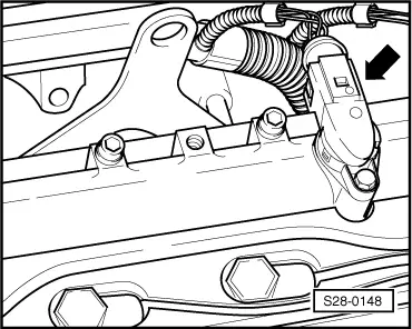
–  Remove engine cover with air filter → Chapter.
Engines with engine identification characters BUD
–  Engine cover → 1.4/55; 1.4/59; 1.4/74 Engine - Mechanics → Rep. Gr.15
Continued for all engines
   
–  Disconnect the 3-pin plug connection from Hall sender -arrow-.
  S28-0148
–  Connect the multimeter for voltage measurement to contact 1 (positive) and 3 (earth) of the plug for the Hall sender.
–  Switch on ignition.
Specified value: min. 4.5 V
–  Switch off ignition.
If no voltage is present:
–  Connect test box -V.A.G 1598/31- or - V.A.G 1598/22- to the wiring loom of the control unit → Chapter.
  S28-0149
–  Check wiring between the test box and the 3-pin plug for interruption according to the current flow diagram → Current flow diagrams and Fitting locations.
Cable resistance: max. 1.5 Ω
–  Test the cables for short circuiting with each other.
Specified value: ∞ Ω
If no fault was found in the cables and the specified voltage measured between contacts 1 + 3:
–  Replace hall sender -G40- → Chapter.
If no fault was detected in the wiring and if there was no voltage between contact 1 + 3:
–  Replace engine control unit → Chapter.
  S24-0582

Check engine speed sender G28 , remove and install > < Safety measures