skoda Workshop Repair Guides

Skoda Workshop Service and Repair Manuals

Testing lambda probe and lambda control after catalyst > < Lambda control
Testing lambda probe and lambda control upstream of catalytic converter
Special tools and workshop equipment required
t  Vehicle system tester -V.A.G 1552 -
t  Diagnostic cable -V.A.G 1551/3, 3A, 3B, 3C-
t  Hand multimeter (e.g. -V.A.G 1526 A-)
t  Adapter cable set (e.g. -V.A.G 1594 A-)
Test conditions
l  The fuel pump relay must be OK.
   
l  
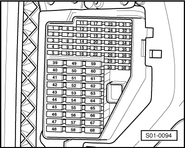
Fuse No. 9 must be o.k.
l  Coolant temperature minimum 80°C
l  No leaks in exhaust system between catalytic converter and cylinder head
l  Battery voltage at least 11.5 V.
Check for proper operation
–  Check display groups 030, 031, 032, 033, 034, 041 and 099 → Chapter or generate readiness code → Chapter.
If the specified value is not reached:
–  Perform a test drive to clear the lambda probe of possible residual values and repeat the test.
If the specification is also not shown in the display field after a test drive:
Testing heater
  S01-0094
–  Disconnect the plug connection on the lambda probe -G39--arrow-.
Engines with engine identification characters AUA, AUB, BBY, BBZ, BKY
  S24-0347
–  Perform a continuity test (resistance measurement) between the contacts of the 6-pin plug at the lambda probe -G39- with the handheld multimeter according to the current flow diagram → Current flow diagrams and Fitting locations.
Engines with engine identification characters BUD
  S24-0346
–  Perform a continuity test (resistance measurement) between the contacts of the 4-pin plug at the lambda probe -G39- with the handheld multimeter according to the current flow diagram → Current flow diagrams and Fitting locations.
Continued for all engines
  Note
At ambient temperature (approx. 20 °C) the heating element resistance is of approx. 1 to 5 Ω. The resistance increases considerably even if the temperature rises only slightly.
–  Replace the lambda probe -G39- if an open circuit is detected.
If the heating element has continuity, test voltage supply for lambda probe heater -Z19- → Current Flow Diagrams, Fault Finding and Fitting Locations.
Test basic voltage
–  Disconnect the plug connection at the lambda probe -G39-.
Engines with engine identification characters AUA, AUB, BBY, BBZ, BKY
  S24-0586
–  Connect the handheld multimeter, for voltage measurement, to the contacts of the 6-pin plug on the wiring loom according to the current flow diagram → Current flow diagrams and Fitting locations.
Engines with engine identification characters BUD
  S24-0592
–  Connect the handheld multimeter, for voltage measurement, to the contacts of the 4-pin plug on the wiring loom according to the current flow diagram → Current flow diagrams and Fitting locations.
Continued for all engines
–  Leave engine on and measure the supply voltage.
Specified value: 0.40 up to 0.50 V
–  Switch off ignition.
If the specified value is not reached:
–  Check lambda probe wire upstream of catalytic converter → Current flow diagrams and Fitting locations.
If the specified value is reached:
–  Replace lambda probe -G39- → 1.4/55; 1.4/59; 1.4/74 Engine - Mechanics → Rep. Gr.26.
  S24-0581

Testing lambda probe and lambda control after catalyst > < Lambda control