skoda Workshop Repair Guides

Skoda Workshop Service and Repair Manuals

Ignition system, glow plug system > < Checking the data BUS
Testing cruise control system
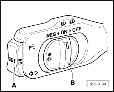
Apart from the control switch on the steering column switch the cruise control system (CCS) has no other components. All functions are carried out by the engine control unit. The data from the operating switch to the engine control unit are transferred over the databus by the electrical system control unit -J519-. The CCS is active above a speed of 30 km/h.
Special tools and workshop equipment required
t  Vehicle system tester -V.A.G 1552-
t  Diagnostic cable -V.A.G 1551/3, 3A, 3B oder 3C-
t  Hand multimeter (e.g. -V.A.G 1526 A-)
t  Adapter cable set (e.g. -V.A.G 1594 C-)
t  Test box -V.A.G 1598/31-
Test condition
l  Fuse No. 28 OK
l  Cruise control activated.
–  Activate the cruise control → Chapter
Check for proper operation
–  Connect vehicle system tester -V.A.G 1552-. Switch ignition on and then select “address word” 01 Engine electronics → Chapter.
–  Select function 08 “Read measured value block” and display group 006.
   
–  Readout on display:
–  Note the contents of indicator 4.
   Specified value:
   0 = CCS disconnected
   1 = CCS connected
–  If the display does not occur as described:
–  Select function 06 “End output” and confirm with Q.
–  Switch off ignition.
 
Reading measured value block         6   ->
0 km/h       000         0 %          0
–  Inspect the CC switch with the hand multimeter (resistance measurement) according to the following table:
  N23-0199
CCS switch10-pin plug on CCS switch, contactSpecification
Switch B on “ON”4 + 5
6 + 7
max. 1.5 Ω
Switch B on “RES”4 + 5
2 + 7
6 + 7
max. 1.5 Ω
Switch A pressed3 + 7max. 1.5 Ω
Switch B pressed to “OFF”6 + 7
4 + 5
max. 1.5 Ω
∞ Ω
Switch B to “OFF” locked6 + 7
2 + 7
4 + 5
∞ Ω

–  Test the wires of the CCS switch to the vehicle voltage control unit -J519- according to the current flow diagram.
   
–  Test the wire from the CCS switch to fuse 28 for interruption or short-circuit.
–  Connect test box -V.A.G 1598/31 - to the engine control unit. The control unit wiring loom is not connected → Chapter.
–  Test the following cable connections for open circuit and for short circuit to earth and to positive:
  S01-0094
10-pin CC plug contactTest box - V.A.G 1598/31-, bush
414
714

If the lines are not found to be faulty:
–  Perform self-diagnosis of onboard supply control unit -J519- → Electrical System; Rep. Gr.90
–  Checking the data BUS → Chapter
   

Ignition system, glow plug system > < Checking the data BUS