Fabia Mk1
|
|
|
|
|
|
|
|
|
|
|
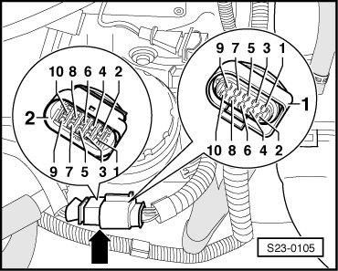
| Connector -1-, contact | Test box -V.A.G 1598/31-, bush | |
| 4 | 103 | |
| 7 | 111 |
|

|
|
|
|
|
|
|
|
|
|
|
| Connector -1-, contact | Test box -V.A.G 1598/31-, bush | |
| 4 | 103 | |
| 7 | 111 |
|