skoda Workshop Repair Guides

Skoda Workshop Service and Repair Manuals

Inspecting the change-over of the intake manifold flap > < Testing Fuel temperature sender G81
Testing the air mass meterG70
Testing the air mass meter -G70-
The air mass meter signal is required by the control unit to calculate the allowed injection rate and to control the exhaust gas recirculation. The lower the signal from the air mass meter the less fuel may be injected.
Special tools and workshop equipment required
t  Vehicle system tester -V.A.G 1552 -
t  Diagnostic cable -V.A.G 1551/3, 3A, 3B oder 3C-
t  Hand multimeter (e.g. -V.A.G 1526 A-)
t  Adapter cable set (e.g. -V.A.G 1594 C-)
t  Test box -V.A.G 1598/31-
Test sequence
–  Connect vehicle system tester -V.A.G 1552-. Start engine (idle) and enter address world 01 “Engine electronics” → Chapter.
–  Select function 08 “Read measured value block” and display group number 010.
   
–  Observe display in display field 1.
   Specified value: 200 through to 320 mg/h
If the specified value is not reached:
–  Testing exhaust gas recirculation → Chapter
If the specified value is reached:
  Note
The V.A.G 1552 should be operated by a second person.
–  The vehicle should be accelerated in such a way that engine revolutions of 1,500 rpm are achieved when the accelerator pedal is fully pressed down (in second gear for a vehicle with manual gearbox, in lever selection position 2 for an automatic gearbox).
–  At approx. 3000 rpm read off display fields 1 and 4. The accelerator pedal (display field 4) must be fully pressed down at this stage.
 
Reading measured value block         10   ->
209 mg/stroke  989.mbar  999.mbar 0.0 %
Readout on display:
   Specified value display field 1: above 700 mg/s
   Specified value display field 4: 100 %
If the nominal value in display field 1 is not reached:
–  Replace the air mass meter -G70-.
If display field 1 constantly displays 550 mg/stroke (fixed replacement temperature):
–  Select function 06 “End output” and confirm entry with Q.
–  Switch off ignition.
 
Reading measured value block         10   ->
780 mg/stroke  989.mbar  999.mbar 100 %
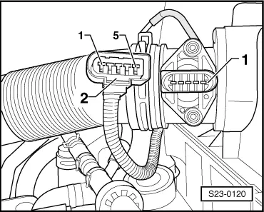
–  Unplug connector -1- at air mass meter -G70--2-.
–  Switch on ignition.
–  Measure the voltage being applied to the following contacts using the hand multimeter:
  S23-0120
Connector -1-, contactSpecification 
2 + earthapprox. battery voltage 
2 + 3approx. battery voltage
4 + earthapprox. 5 V
4 + 3approx. 5 V

If the specified values are not reached:
–  Switch off ignition.
–  Connect test box -V.A.G 1598/31 - to the wiring loom on the engine control unit → Chapter.
   
–  Check the following wire for interruption or short-circuit to earth or positive:
  S23-0120
Connector -1-, contactTest box -V.A.G 1598/31-, bush 
21 + 2 (when ignition is on) 
349
430
568

–  Also check the wires for short-circuits.
–  If necessary eliminate wire interruption or short-circuit.
If the lines are not found to be faulty:
–  Replacing engine control unit -J248- → Chapter.
   

Inspecting the change-over of the intake manifold flap > < Testing Fuel temperature sender G81