skoda Workshop Repair Guides

Skoda Workshop Service and Repair Manuals

Connection for the quick-coupling adapter on the refrigerant circuit > < Structure of the refrigerant circuit
Parts of the refrigerant circuit
   
Compressor
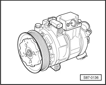
The new, externally controlled compressor 6 SEU 12C with variable displacement is driven by the engine's ribbed V-belt. It does not have a magnetic clutch.
The belt pulley/compressor shaft grip occurs via a driver clutch.
The displacement of the compressor is controlled via an externally driven regulating valve with PWM signal on the suction side in accordance with the required cooling output.
The compressor continues operating with a minimum power supply requirement even when the air conditioning system is off.
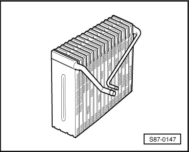
The compressor sucks refrigerant gas from the evaporator, compresses it and transfers it to the condenser.
  Note
The compressor contains refrigerant oil, which can be mixed with the R 134a refrigerant at all temperatures.
  S87-0136
Condenser
The condenser dissipates heat from the compressed refrigerant gas into the ambient air.
During this process the refrigerant gas condenses and liquifies.
  S87-0137
Fluid reservoir for vehicles up to 05.04
The fluid reservoir -4- is a component part of the condenser.
It gathers the liquid drops and conveys them to the expansion valve in a constant flow.
Humidity, that has penetrated into the refrigerant circuit during assembly, is bound by a dessicator insert -3- in the fluid reservoir.
  S87-0139
Fluid reservoir for vehicles as of 06.04
The fluid reservoir -6- is a component part of the condenser.
It gathers the liquid drops and conveys them to the expansion valve in a constant flow.
Humidity, that has penetrated into the refrigerant circuit during assembly, is bound by a dessicator insert -5- in the fluid reservoir.
  S87-0285
Expansion valve
The expansion valve atomizes incoming refrigerant and controls the flow in accordance with the different pressures in such a way that, depending on the heat transport, the vapour only becomes gaseous at the outlet of the evaporator.
  Note
The expansion valves for refrigerant circuits using refrigerant R 134a are indicated with green sticker.
  S87-0140
Evaporator
The liquid refrigerant evaporates in the evaporator. The heat required for this operation is drawn from the air flowing through the evaporator fins.
The air cools down the evaporator. The refrigerant evaporates and is sucked in with the absorbed heat as gas by the compressor.
The externally regulated compressor allows a variable air outlet temperature of 1 to 11°C.
Tubes and hoses of the refrigerant circuit
The mixture of refrigerant oil and refrigerant R 134a corrodes certain metals (e.g. copper) and alloys and dissolves certain hose materials.
Therefore only original spare parts may be used.
  Note
Pay attention to the prescribed tightening torques for the screwed connections.
  S87-0147
O-ring seals
These O-rings seal off the connection points between the individual components of the refrigerant circuit.
Only use O-rings that are resistant to refrigerant R 134a and related refrigerant oils. Original spare parts offer this guarantee.
Black and coloured O-rings are fitted.
O-ring seals:
t  Only use once, replace.
t  Pay attention to correct diameter -a- and -b-.
t  Moisten with refrigerant oil before inserting.
  S87-0033

Connection for the quick-coupling adapter on the refrigerant circuit > < Structure of the refrigerant circuit