
Fabia Mk1
 Note
Note
|
| Refrigerant circuit with expansion valve and fluid reservoir |
Note| The expansion valve is removed and is replaced by an adapter. The fluid reservoir must be removed depending on the vehicle and the line connections to the fluid reservoir must connect with each other using two adapters and a filling hose. |
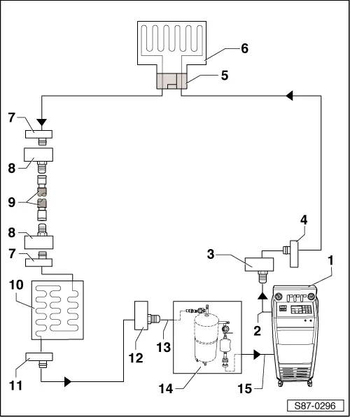
| 1 - | A/C service station |
| q | With electronics and a program for flushing or with a flushing system. |
| q | If an A/C service station without a program for flushing is used, the procedure must be performed manually (evacuate, flush three times, at least 4 kg each time and drain the refrigerant again). |
| 2 - | Refrigerant hose of the A/C service station |
| q | From the high-pressure side of the A/C service station (usually red in colour) to the connection for the low-pressure side of the AC compressor (larger diameter). |
| 3 - | Adapter to connection for the low-pressure side |
| q | Different versions depending on the vehicle. |
| q | From the adapter case of the motor car set -VAS 6338/1-. |
| 4 - | Connection of the low-pressure side on the refrigerant circuit to the compressor |
| q | Different versions depending on the vehicle. |
| 5 - | Adapter for the installed expansion valve |
| q | Different versions depending on the vehicle. |
| q | From the adapter case of the motor car set -VAS 6338/1-. |
| 6 - | Evaporator |
| 7 - | Connection to the fluid reservoir |
| q | Different versions depending on the vehicle. |
| q | Not available on vehicles with a dessicator cartridge in the fluid reservoir at the condenser or with a fluid reservoir installed in the condenser. |
| 8 - | Adapter for bridging the removed fluid reservoir |
| q | Not required on all vehicles (see the above-mentioned point). |
| q | Different versions depending on the vehicle. |
| q | From the adapter case of the motor car set -VAS 6338/1-. |
| 9 - | Filling hose for refrigerant |
| q | From the adapter case of the motor car set -VAS 6338/1-. |
| 10 - | Condenser |
| q | If a fluid reservoir with dessicator cartridge is installed at the condenser, the dessicator cartridge must be removed (close again after removing fluid reservoir at or in the condenser). |
| 11 - | Connection of the high-pressure side on the refrigerant circuit to the compressor |
| q | Different versions depending on the vehicle. |
| 12 - | Adapter to connection for the high-pressure side of the refrigerant circuit |
| q | Different versions depending on the vehicle. |
| q | From the adapter case of the motor car set -VAS 6338/1-. |
| 13 - | Filling hose of flushing device for the refrigerant circuits |
| q | From connection to high-pressure side of the compressor in the refrigerant circuit (smaller diameter) to inlet of flushing system for the refrigerant circuits. |
| 14 - | Flushing device for the refrigerant circuits |
| q | E.g -VAS 6336/1- or -VAS 6337/1- (different versions and different structures). |
| q | With filter, inspection glass, safety valve, heating, refrigerant reservoir etc. (depending on the version). |
| q | Depending on the structure of the A/C service station and the flushing device for the refrigerant circuits, a non-return valve can be installed on the outlet of the flushing device for the refrigerant circuits (in order to ensure the correct flow direction of the refrigerant when flushing). |
| 15 - | Refrigerant hose of the A/C service station |
| q | From the low-pressure side of the A/C service station (usually blue in colour) to the outlet of the flushing device for the refrigerant circuits. |
| Refrigerant circuit with throttle and catch pan |
Note| The throttle is removed and the refrigerant pipes are assembled again. The catch pan is also removed and the line connections to the reservoir are connected together again. To do so, use the adapter and the filling hose from the adapter case of the motor car set -VAS6338/31-, see → Chapter. |

| 1 - | A/C service station |
| q | with electronics and a program for flushing or with a flushing system |
| q | if an A/C service station without a program for flushing is used, the procedure must be performed manually (evacuate, flush three times, at least 4 kg each time and drain the refrigerant again) |
| 2 - | Refrigerant hose of the A/C service station |
| q | from the high-pressure side of the A/C service station (usually red in colour) to the connection for the low-pressure side of the AC compressor (larger diameter) |
| 3 - | Adapter to connection for the low-pressure side |
| q | different versions depending on the vehicle |
| q | from the adapter case of the motor car set -VAS 6338/1- |
| 4 - | Connection of the low-pressure side on the refrigerant circuit to the compressor |
| q | different versions depending on the vehicle |
| 5 - | Connection to the catch pan |
| 6 - | Adapter for bridging the removed catch pan |
| q | from the adapter case of the motor car set -VAS 6338/1- |
| 7 - | Filling hose for refrigerant |
| q | from the adapter case of the motor car set -VAS 6338/1- |
| 8 - | Adapter for bridging the removed catch pan |
| q | from the adapter case of the motor car set -VAS 6338/1- |
| 9 - | Connection to the catch pan |
| 10 - | Evaporator |
| 11 - | Fitting location of the throttle |
| q | the throttle is removed |
| q | Removing and installing the throttle → Heating, Air Conditioning → Rep. gr.87 |
| 12 - | Screwed connection in the refrigerant line |
| q | screw together again after the removal of the throttle |
| 13 - | Condenser |
| 14 - | Connection of the high-pressure side on the refrigerant circuit to the compressor |
| q | e.g -VAS 6336/1- or -VAS 6337/1- (different versions and different structures) |
| 15 - | Adapter to connection for the high-pressure side of the refrigerant circuit |
| q | from the adapter case of the motor car set -VAS 6338/1- |
| 16 - | Filling hose of flushing device for the refrigerant circuits |
| q | from the connection to the high-pressure side of the AC compressor on the refrigerant circuit (smaller diameter) to inlet of flushing device for the refrigerant circuits |
| 17 - | Flushing device for the refrigerant circuits |
| q | e.g -VAS 6336/1- or -VAS 6337/1- (different versions and different structures) |
| q | with filter, inspection glass, safety valve, heating, refrigerant reservoir etc. (depending on the version) |
| q | depending on the structure of the A/C service station and the flushing device for the refrigerant circuits, a non-return valve can be installed on the outlet of the flushing device for the refrigerant circuits (in order to ensure the correct flow direction of the refrigerant when flushing) |
| 18 - | Refrigerant hose of the A/C service station |
| q | from the low-pressure side of the A/C service station (usually blue in colour) to the outlet of the flushing device for the refrigerant circuits |