skoda Workshop Repair Guides

Skoda Workshop Service and Repair Manuals

Tightening torques > < Disassembling planetary gear
Assembling planetary gear
–  Insert the axial needle bearing in the fitting position → Chapter.
–  Assembling drive gear and ring gear → Chapter.
   
–  Insert overrunning clutch complete with thrust washers -C-.
   Pay attention to the fitting position when inserting the overrunning clutch → Chapter.
–  Secure overrunning clutch with circlip -B-.
–  Install drive gear with ring gear -A- in the gearbox housing.
–  Insert the new lock washer with the pegs of the washer in the gearbox housing holes.
  S37-0098
–  Tighten tensioning screw to 60 Nm.
1 - Torque wrench (40...200 Nm), e.g. -V.A.G 1332-
–  Secure tensioning screw with lock washer.
  S37-0097
–  Insert the planet carrier -B- in the drive gear with ring gear and simultaneously in the overrunning clutch.
  Note
When inserting in the overrunning clutch rotate the planet carrier anti-clockwise (turn left).
–  Inspect operation of overrunning clutch:
   The planet carrier must only be turned anti-clockwise (overrunning clutch open).
–  Place the axial needle bearing -A- in its fitting location (black surface remains visible) on the planet carrier -B-.
  S37-0094
–  Install plates -B1- as follows:
t  First place a suitable pressure plate → Chapter-5- on the circlip -6-.
t  Insert inner plates -7- and outer plates -4- of -B1-.
t  Place thrust plate -3-.
t  Insert the disc springs -2- in their fitting position (large diameters point towards one another).
t  Fit circlip -1-.
  N38-0106
–  3. Insert the 3rd through 4th gear-clutch -A-.
–  Fit new O-rings -arrows- to the gearbox housing.
  S37-0116
–  Press spring support plate onto the guide studs of the piston -B1-.
One guide stud -A- is thicker than the others and thus holds the spring support plate in place.
–  Moisten the axial needle bearing -B- with ATF to ensure the bearing sticks to the gearbox housing cover when fitted.
Insert the axial needle bearing in its fitting position (black surface remains visible) on the cover.
–  Apply sealant -D 176 404 A2- to the clean sealing surface of the cover.
–  The sealant bead must be 3...4 mm thick.
–  Fit cover for gearbox housing.
  N37-0619
–  Subsequently, tighten the screws crosswise with 20 Nm.
–  Rotate gearbox in assembly stand -MP 9-101- 180°.
  S37-0092
–  Insert input shaft -1-.
  N37-0580
–  Insert the large sun gear -B- in the gearbox housing.
–  Place the axial needle bearing -A- in its fitting location (smooth surface remains visible) on the large sun gear.
  N37-0579
–  Insert drive shaft -2- in large sun gear.
–  Place the axial needle bearing -1- in its fitting location (black surface remains visible) on the drive shaft.
  N37-0578
–  Insert the 1st through 3rd gear-clutch -B-.
Insert the axial needle bearing -A- in its fitting position (black surface remains visible) in the 1st through 3rd gear-clutch.
When replacing individual components of the planetary gear, measure the axial needle bearing again → Chapter, adjust clutch clearance.
  N37-0577
–  Insert reverse gear-clutch -1-.
   To do so the recesses -arrow A- of the reverse gear-clutch must catch in the pegs -arrow B- of the large sun gear.
  S37-0099
–  Place the adjusting washer -2- on the reverse gear-clutch -K1-.
When replacing individual components of the planetary gear, measure the adjusting washer again → Chapter, adjust clutch clearance.
–  Insert gasket -1- for ATF pump.
  N37-0574
Install the brake band as follows:
–  Fit brake band -3-.
–  Insert new adjusting screw -2- with counternut -1- at gearbox.
Do not yet screw in the coated part of the screw thread. Final tightening of the adjusting screw must not occur until the ATF pump has been installed → Chapter, adjust 2nd and 4th gear-brake -B2-.
–  Align ATF pump with gearbox housing. When inserting pay attention to the adjusting washer, gasket for ATF pump and piston rings of the ATF pump.
  S37-0091
–  Tighten screws of the ATF pump -arrows- to 20 Nm.
  N37-0573
–  Insert the differential gear -arrow A-.
–  Place new O-rings -arrow B- on the gearbox housing and insert in turbine shaft -arrow C-.
–  Apply sealant -D 176 404 A2- to the clean sealing surface of the converter housing.
   The sealant bead must be 3...4 mm thick.
–  Position the converter housing on the gearbox housing, pay attention to the fit pin and O-ring of the ATF pump.
  N37-0570
–  Tighten the converter housing screws to 30 Nm.
–  Install the left and right flange shafts -arrow-.
–  Install the plug connection with wiring loom for the solenoid valves.
–  Moisten the O-rings with ATF.
  S37-0090
–  Insert new O-rings -A- in the gearbox housing.
  N37-0617
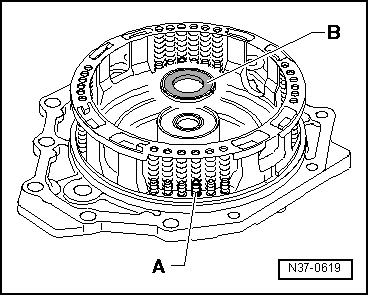
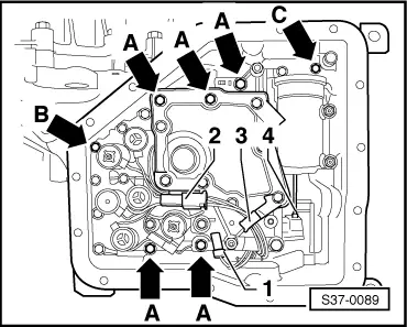
–  Fit slide valve body and insert the bolt of the shift segment in the slot of the manual slider -4-.
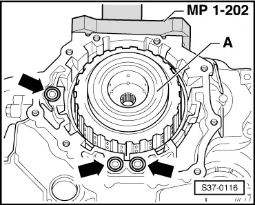
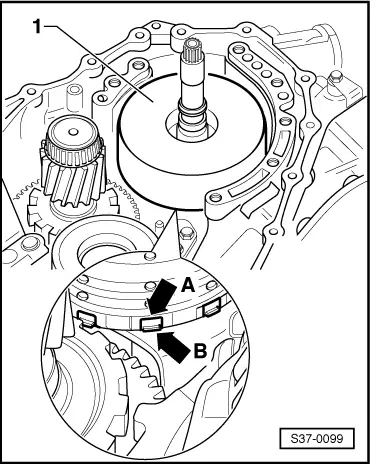
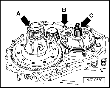
–  Tighten screws -arrows A through C- by hand, pay attention to the different screw lengths.
t  Screws -arrows A- = M6 x 80 mm
t  Screw -arrow B- = M6 x 68 mm
t  Screw -arrow C- = M6 x 40 mm
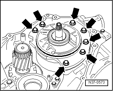
–  Subsequently, tighten the screws gradually and crosswise to 8 Nm.
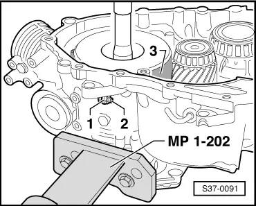
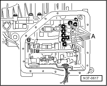
–  Insert plug for the solenoid valves -2-.
–  Hook wiring loom onto bracket -3-.
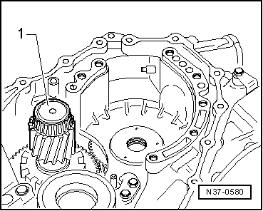
–  Clip on sender -1- for ATF temperature.
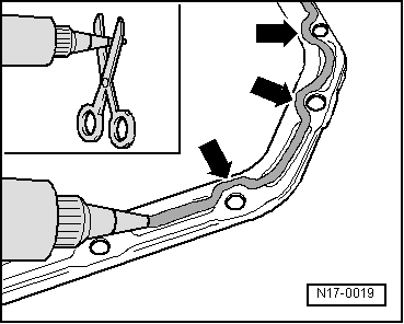
Apply sealant -D 176 404 A2- to the oil pan as follows:
  S37-0089
–  Cut off nozzle tube at the front marking (Ø of nozzle approx. 3 mm).
–  Apply sealant as shown to the clean sealing surface of the oil pan.
   The sealant bead must be 3...4 mm thick.
   Run past the area around the bolt holes on the inside -arrows-.
–  Install oil pan.
  N17-0019
–  Install ATF radiator on gearbox -arrow-.
–  Installing the torque converter → Chapter.
–  Installing and setting multi-function switch → Chapter.
–  nstalling electrical connections and sender on gearbox → Chapter.
–  Installing the gearbox → Chapter.
–  Fill with ATF and check and top up ATF level → Chapter.
  S37-0088

Tightening torques > < Disassembling planetary gear