
Fabia Mk1
 Note
Note| t | When installing new pinions or a new output shaft observe the technical data → Chapter. |
| t | Insert all bearings, gears and synchronizer rings in the gearbox with gear oil. |
| t | Do not interchange the synchronizer rings. If re-used always assign to the original gear. |

| 1 - | Nut, 60 Nm |
| q | always replace |
| 2 - | Disc spring |
| q | Fitting position: curved side points to gearbox housing cover |
| 3 - | Supporting ring |
| 4 - | Spring |
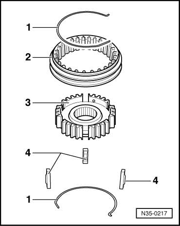
| q | Fitting position → Fig. |
| 5 - | 5th gear sliding sleeve |
| q | removing and installing → Fig. and → Fig. |
| 6 - | 5th gear synchronizer body |
| q | removing and installing → Fig. and → Fig. |
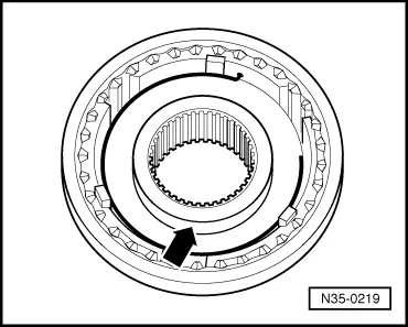
| 7 - | Arresters (3 pieces) |
| q | Fitting position → Fig. |
| 8 - | 5th gear synchronizer ring |
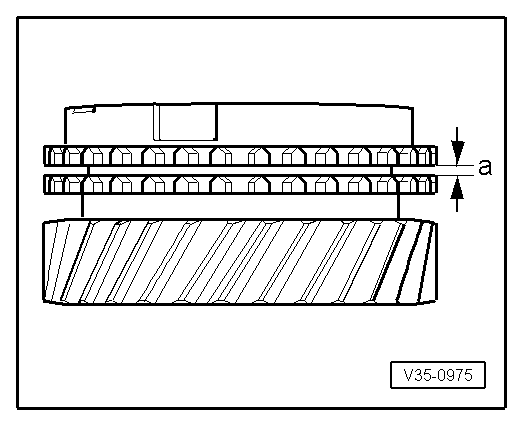
| q | check for wear → Fig. |
| 9 - | 5th gear sliding gear |
| 10 - | Needle bearing |
| 11 - | Bushing for needle bearing |
| q | Fitting position: The oil pockets -arrow- point towards the 5th gear synchronizer body. |
| 12 - | Gearbox housing |
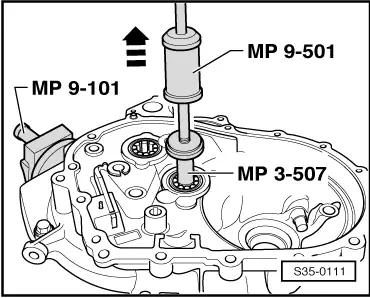
| 13 - | Grooved ball bearing |
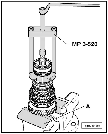
| q | remove → Fig. |
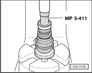
| q | pressing on → Fig. |
| 14 - | 4th gear sliding gear |
| 15 - | Circlip |
| q | replace |
| 16 - | 4th gear synchronizer ring |
| q | check for wear → Fig. |
| 17 - | Spring |
| 18 - | Sliding sleeve 3rd and 4th gear |
| 19 - | Synchronizer body for 3rd and 4th gear |
| 20 - | Arresters for synchronizer body (3 pieces) |
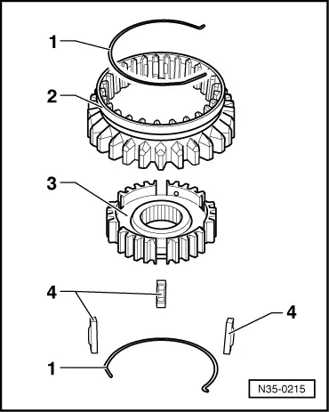
| 21 - | Sliding sleeve with 3rd and 4th gear synchronizer body |
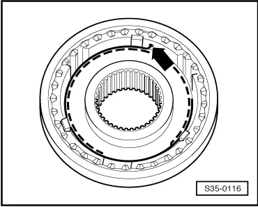
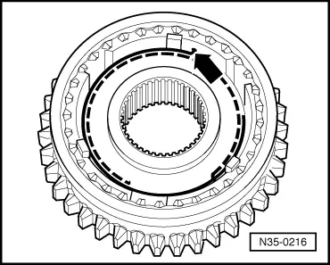
| q | Assembling the sliding sleeve with synchronizer body → Fig. and → Fig. |
| q | Fitting position of the sliding sleeve with synchronizer body → Fig. |
| 22 - | 3rd gear synchronizer ring |
| q | check for wear → Fig. |
| 23 - | 3rd gear sliding gear |
| 24 - | Washer |
| q | holds the thrust washers → Item in the correct position on the output shaft |
| 25 - | 2nd and 3rd gear thrust washers |
| 26 - | 2nd gear sliding gear |
| 27 - | 2nd gear synchronizer ring |
| q | check for wear → Fig. |
| 28 - | Sliding sleeve with 1st and 2nd gear synchronizer body |
| q | Assembling the sliding sleeve with synchronizer body → Fig. and → Fig. |
| 29 - | 1st gear synchronizer ring |
| q | check for wear → Fig. |
| 30 - | 1st gear sliding gear |
| 31 - | Output shaft |
| q | is paired with the gear pinion of the final drive, always replace together |
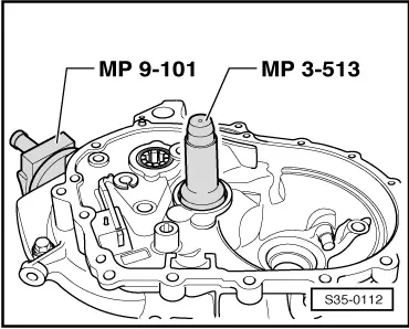
| 32 - | Cylindrical-roller bearing |
| q | removing → Fig. |
| q | pressing on → Fig. |
| q | Fitting position: the marking on the bearing points upwards |
| 33 - | Supports |
| q | for oil supply |
| 34 - | Washer |
| 35 - | 10 Nm |
| 36 - | Clutch housing |
|
|
|
|
|
|
|
|
|
|
|
|
|
|
|
|
| Fitting dimension | Wear limit | |
| Clearance “a” | 1,2 to 1,8 mm | 0,5 mm |
|
|
|
|