
Fabia Mk1
 Note
Note
|

| 1 - | Circlip |
| q | always replace → Electronic Catalogue of Original Parts |
| q | Determine thickness → Chapter |
| 2 - | Sliding sleeve with 5th gear synchronizer body |
| q | removing and installing → Chapter |
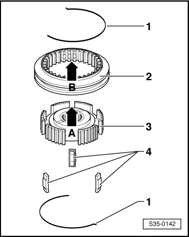
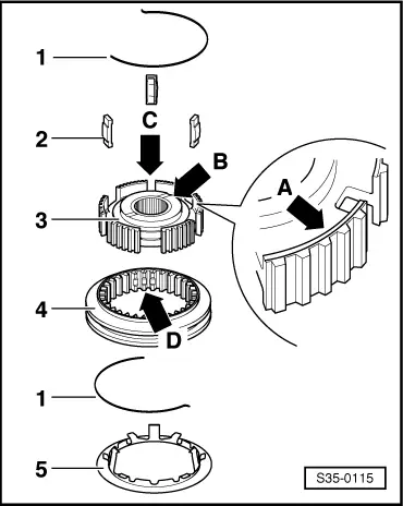
| q | disassembling → Fig. |
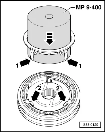
| q | Assembling sliding sleeve with 5th gear synchronizer body → Fig. and → Fig. |
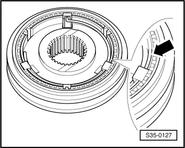
| 3 - | 5th gear synchronizer ring |
| q | check for wear → Fig. |
| 4 - | 5th gear sliding gear |
| 5 - | Needle bearing |
| q | for 5th gear |
| q | replace together with bushing Pos. 6 |
| q | Assignment → Electronic Catalogue of Original Parts |
| 6 - | Bushing |
| q | for 5th gear needle bearing |
| q | replace together with needle bearing Pos. 5 |
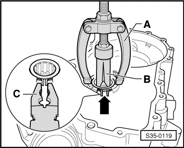
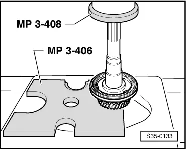
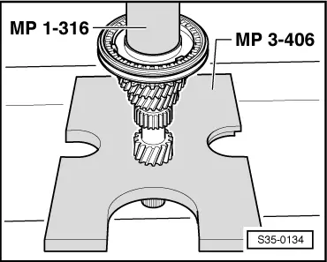
| q | press off with bearing support for grooved ball bearing → Fig. |
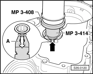
| q | pressing on → Fig. |
| q | Assignment → Electronic Catalogue of Original Parts |
| 7 - | Gearbox housing |
| 8 - | Bearing support for grooved ball bearing |
| q | If the bearing support is released from the gearbox housing, it must always be replaced |
| q | Only replace grooved ball bearing together with the bearing support → Electronic Catalogue of Original Parts |
| q | pressing off → Fig. |
| q | pressing on → Fig. |
| 9 - | Drive shaft |
| 10 - | Needle bearing |
| q | for 3rd gear |
| 11 - | 3rd gear sliding gear |
| 12 - | 3rd gear synchronizer ring |
| q | check for wear → Fig. |
| 13 - | Circlip |
| q | installed on certain gearboxes, assign via → Electronic Catalogue of Original Parts |
| q | pushing out → Fig. |
| q | inserting → Fig. |
| 14 - | Sliding sleeve with 3rd and 4th gear synchronizer body |
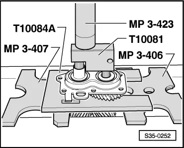
| q | press off with 3rd gear sliding gear → Fig. |
| q | disassembling → Fig. |
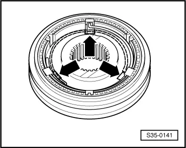
| q | Fitting position sliding sleeve/synchronizer body → Fig. |
| q | Assemble sliding sleeve/synchronizer body → Fig. and → Fig. |
| q | pressing on → Fig. |
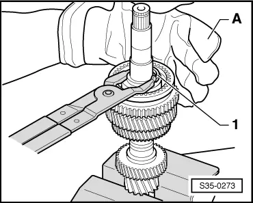
| 15 - | Circlip |
| q | installed on certain gearboxes, assign via → Electronic Catalogue of Original Parts |
| q | pushing out → Fig. |
| q | inserting → Fig. |
| 16 - | 4th gear synchronizer ring |
| q | check for wear → Fig. |
| 17 - | 4th gear sliding gear |
| 18 - | Needle bearing |
| q | for 4th gear |
| q | on certain gearboxes a needle bearing Pos. 24 is installed together with a bushing Pos. 25, assign via → Electronic Catalogue of Original Parts |
| 19 - | Thrust washer |
| 20 - | Inner ring |
| q | for cylindrical-roller bearing |
| q | press off with 4th gear sliding gear → Fig. |
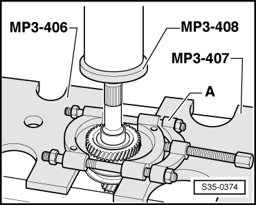
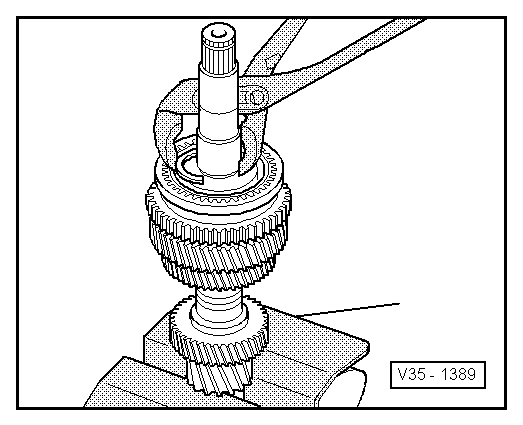
| q | pressing on → Fig. |
| 21 - | Circlip |
| q | replace → Electronic Catalogue of Original Parts |
| q | Determine thickness → Fig. |
| 22 - | Cylindrical-roller bearing |
| q | with circlip |
| q | removing → Fig. |
| q | pressing on → Fig. |
| q | Fitting position: the circlip in the bearing points towards the drive shaft |
| 23 - | Clutch housing |
| 24 - | Needle bearing |
| q | for 4th gear |
| q | installed on certain gearboxes |
| q | replace together with bushing Pos. 25 for 4th gear. |
| 25 - | Bushing |
| q | for 4th gear needle bearing |
| q | replace together with needle bearing Pos. 24 |
| q | installed on certain gearboxes |
| q | Pressing off bushing for needle bearing with sliding sleeve/synchronizer body for 3rd and 4th gear → Fig. |
| q | Pressing on bushing for needle bearing → Fig. |
| 26 - | Spring |
| q | Fitting position → Fig. |
| 27 - | Sliding sleeve 3rd and 4th gear |
| 28 - | Synchronizer body for 3rd and 4th gear |
| 29 - | Arresters for synchronizer body |
| q | (3 pieces) |
| 30 - | Spring |
| q | Fitting position → Fig. |
| 31 - | Arresters for synchronizer body |
| q | (3 pieces) |
| 32 - | 5th gear synchronizer body |
| 33 - | 5th gear sliding sleeve |
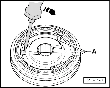
| 34 - | Stop ring |
| q | prevents the arresters from wandering |
| q | removing → Fig. |
| q | installing → Fig. |
|
|
Note
|
|
|
|
Note
|
|
 WARNING
Note
|
|
|
|
|
|
|
|
|
|
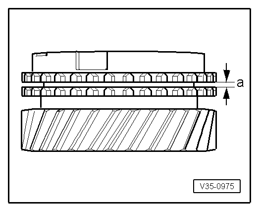
| Fitting dimension | Wear limit | |
| Clearance -a- | 1.1…1.7 mm | 0.5 mm |
|
|
Note
|
|
|
|
|
|
Note
|
|
| Measured value (mm) | Circlip thickness (mm) | Axial play (mm) |
| 0,05…0,10 | 2,0 | 0,05…0,15 |
| 0,15…0,20 | 2,1 | 0,05…0,15 |
| 0,25…0,30 | 2,2 | 0,05…0,15 |
| 0,35…0,40 | 2,3 | 0,05…0,15 |
| 0,45…0,50 | 2,4 | 0,05…0,10 |
|

|
|
|
|
|
|
|
|
|