
Fabia Mk1

| 1 - | Gearbox housing |
| q | if replaced: Setting the output shafts and differential gear → Chapter |
| q | as of gearbox manufacturing date 08 01 6 the threaded bores for the oil filler plug and oil drain plug are modified from M24 x 1.5 to M22 x 1.5 |
| q | modified as of gearbox manufacturing date 10 04 6 in the area of the support for the grooved ball bearing/drive shaft → Chapter |
| q | assign components via → Electronic Catalogue of Original Parts |
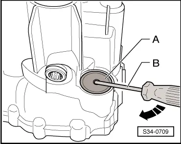
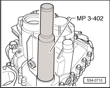
| 2 - | Cap |
| q | removing → Fig. |
| q | inserting → Fig. |
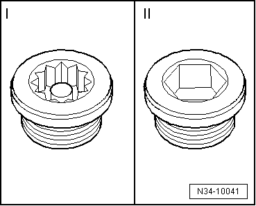
| 3 - | Oil drain plug |
| q | pay attention to different version → Fig. |
| q | Splined nut, 45 Nm |
| q | Allan screw, 30 Nm |
| 4 - | Gasket ring |
| q | always replace → Electronic Catalogue of Original Parts |
| q | no longer applicable for oil filler plug or oil drain plug with thread M22 x 1.5 mm |
| 5 - | Oil filler plug |
| q | pay attention to different version → Fig. |
| q | Splined nut, 45 Nm |
| q | Allan screw, 30 Nm |
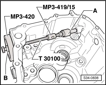
| 6 - | Locking angle |
| q | for setting the gearshift mechanism → Chapter |
| q | can be replaced without disassembling gearbox |
| q | removing → Fig. |
| q | Fitting position → Fig. |
| q | inserting → Fig. |
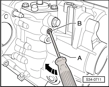
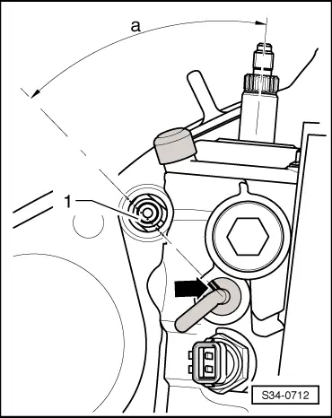
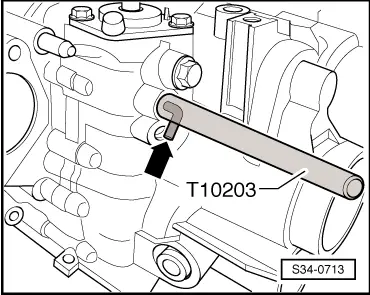
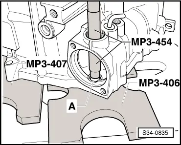
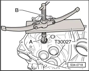
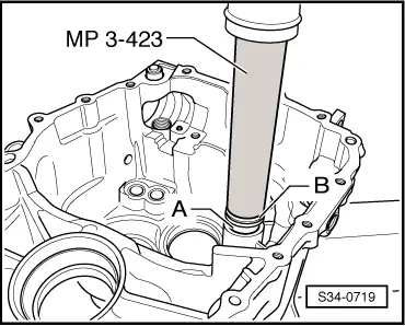
| 7 - | Bushing |
| q | for selector rods |
| q | removing → Fig. |
| q | inserting → Fig. |
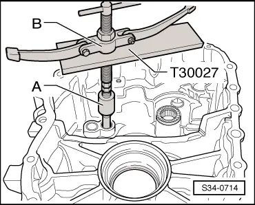
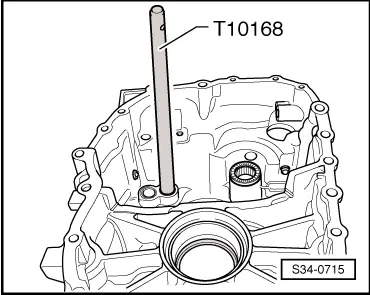
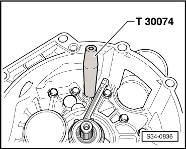
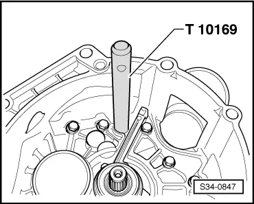
| 8 - | Serrated sleeve |
| q | press out with gearbox disassembled → Fig. |
| q | drive out without disassembling gearbox → Fig. |
| q | inserting → Fig. |
| 9 - | Needle bushing |
| q | for reverse shaft |
| q | replace after each disassembly → electronic catalogue of original parts |
| q | removing → Fig. |
| q | installing → Fig. |
| 10 - | Outer ring/tapered-roller bearing |
| q | for output shaft 5th/6th and reverse gear |
| q | removing and installing → Chapter |
| q | if replaced: Setting output shaft 5th/6th and reverse gear → Chapter |
| 11 - | Adjusting washer |
| q | for output shaft 5th/6th and reverse gear |
| q | Setting overview → Chapter |
| 12 - | Outer ring/tapered-roller bearing |
| q | for output shaft gears 1 through 4 |
| q | removing and installing → Chapter |
| q | if replaced: Setting output shaft gears 1 through 4 → Chapter |
| 13 - | Adjusting washer |
| q | for output shaft gears 1 through 4 |
| q | Setting overview → Chapter |
| 14 - | Outer ring/tapered-roller bearing |
| q | for differential |
| q | removing and installing → Chapter |
| q | if replaced: Adjusting the differential gear → Chapter |
| 15 - | Adjusting washer |
| q | for differential |
| q | Setting overview → Chapter |
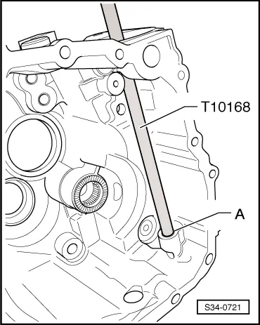
| 16 - | Bushing |
| q | for gearshift shaft |
| q | removing → Fig. |
| q | inserting → Fig. |
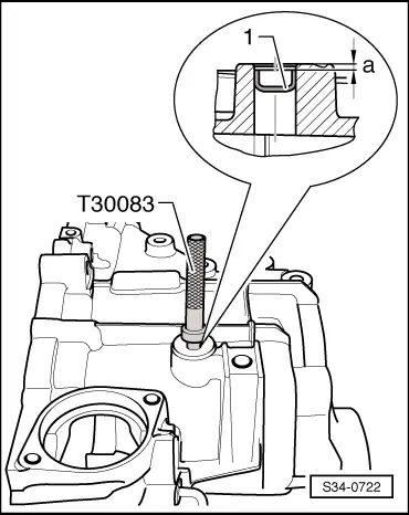
| 17 - | Plug |
| q | drive out with drift |
| q | inserting → Fig. |
| 18 - | Gasket ring |
| q | for left flange shaft |
| q | replace → Chapter |
 Note
Note
|
|
|
|
|
|
|
|
|
|
Note
|
|
|
|
|
|
|
|
|
|
|
|
Note
|
|
|
|
|
|
|
|
|
|