| –
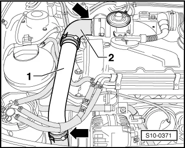
| Remove charge-air pipe at the top -1- with connecting hose -2--arrows-. |
| –
| Remove connecting hose from rear charge air pipe and air filter → Chapter. |
| –
| Removing rear charge air pipe (Pos. 14) with connecting hose to turbocharger → Chapter. |
| –
| Remove the air guide from the lock carrier and the air filter → Chapter. |
| –
| Unscrew the oil feed line from the exhaust turbocharger → Chapter (Pos. 30), → Chapter (Pos. 21). |
| –
| Removing connecting tube inlet connection/exhaust manifold → Chapter. |
| –
| Remove intake manifold with mechanical exhaust gas recirculation valve: |
| t
| For engine with identification characters AMF → Chapter (Pos. 3). |
| t
| For engine with identification characters BNM, BNV → Chapter (Pos. 2). |
| –
| Unscrew pre-exhaust pipe: |
| t
| For engine with identification characters AMF → Chapter (Pos. 26). |
| t
| For engine with identification characters BNM, BNV → Chapter (Pos. 18). |
| –
| Remove the noise insulation. |
| –
| Unscrew the propeller-shaft guard from the cylinder block. |
| –
| Removing bottom charge air pipe (Pos. 19) with connecting hose to turbocharger → Chapter. |
| –
| Pull out vacuum hoses from the exhaust turbocharger → Chapter. |
| –
| Unscrew oil return line from exhaust turbocharger: |
| t
| For engine with identification characters AMF → Chapter (Pos. 23). |
| t
| For engine with identification characters BNM, BNV → Chapter (Pos. 15). |
| t
| For engine with identification characters AMF → Chapter (Pos. 10). |
| t
| For engine with identification characters BNM, BNV → Chapter (Pos. 11). |
| –
| Remove exhaust manifold and take out with turbocharger upwards: |
| t
| For engine with identification characters AMF → Chapter (Pos. 1). |
| t
| For engine with identification characters BNM, BNV → Chapter (Pos. 1). |
| For engine with identification characters AMF |
| –
| Remove turbocharger → Chapter (Pos. 28) from exhaust manifold. |
| Installation occurs in reverse order. Pay attention to the following: |

Note | t
| Tightening torques: for engine with identification characters AMF → Chapter, for engine with identification characters BNM, BNV → Chapter. |
| t
| Always replace self-locking nuts with new ones. |
| t
| Fill exhaust turbocharger with engine oil through the connection fitting of the oil feed line. |
| t
| After installing the exhaust turbocharger, run engine at idling speed for about 1 minute to ensure that oil is supplied to the exhaust turbocharger. |
|
|
|
 Caution