
Fabia Mk1
| Valve gear - Summary of components |

| 1 - | 10 Nm |
| q | only on engines with identification characters BUD |
| 2 - | Protective cover |
| q | only on engines with identification characters BUD |
| 3 - | Guide |
| q | for engines BBY, BBZ, BKY, BUD |
| q | for engines AUA, AUB ignition cable guide → Chapter |
| q | tighten at camshaft housing to 8 Nm |
| 4 - | 20 Nm + torque a further 1/4 turn (90°) |
| q | replace |
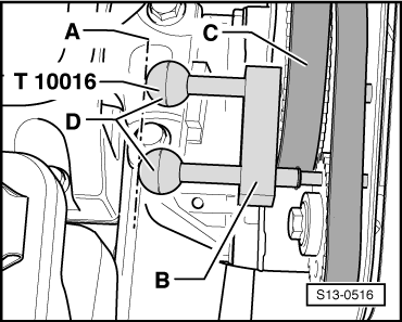
| q | to release and tighten use camshaft lock -T10016- → Fig. |
| 5 - | Camshaft sprocket |
| q | Pay attention to position of toothed belt when installing → Chapter |
| 6 - | Sealing ring |
| q | only replace with the camshaft installed |
| q | Lightly oil sealing lip |
| q | replace → Chapter |
| 7 - | Coupling drive - toothed belt |
| q | before removing mark running direction |
| q | check for wear |
| q | do not kink |
| q | removing and installing, tensioning → Chapter |
| 8 - | 10 Nm + torque a further 1/4 turn (90°) |
| q | replace |
| q | tighten from inside to outside |
| 9 - | Camshaft housing |
| q | for engines BKY, BUD with Hall sender -G40- → Chapter |
| q | removing and installing → Chapter |
| q | when installing, fit onto stud bolts and dowel pins vertically from above. |
| 10 - | Screw cap |
| 11 - | 10 Nm |
| 12 - | Roller rocker arm |
| q | Check smooth operation of cylindrical-roller bearings |
| q | oil contact surface |
| q | for installing, secure locking clip onto hydraulic balancing element |
| 13 - | Collets |
| 14 - | Screw cap |
| 15 - | 20 Nm |
| 16 - | Lifting eye |
| 17 - | Non-return valve, 6 Nm |
| q | Clean thread and install with sealant -D 154 102 A1- |
| q | do not tighten excessively as the valve may tilt |
| 18 - | Hydraulic balancing element |
| q | do not interchange |
| q | with hydraulic valve clearance compensation |
| q | oil contact surface |
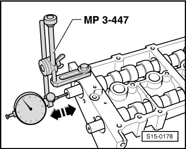
| q | before installing check axial play of the camshafts → Fig. |
| 19 - | Valve spring retainer |
| 20 - | Valve spring |
| q | removing and installing with blank holder for valve spring -MP1-229 (3362)- |
| 21 - | Valve stem seal |
| q | replace → Chapter |
| 22 - | Valve guide |
| q | check → Chapter |
| 23 - | Oil pressure switch -F1-, 25 Nm |
| q | Switching pressure 0.03 ... 0.07 MPa (0.3 ... 0.7 bar) |
| q | check → Chapter |
| q | Cut open gasket ring if leaking and replace |
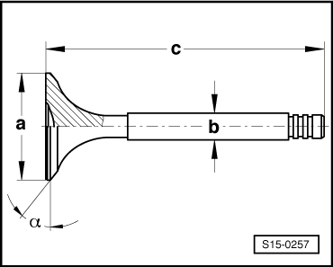
| 24 - | Valves |
| q | do not rework, only grinding in is permissible |
| q | Valve dimensions → Fig. |
| 25 - | Cylinder head |
| q | reworking valve seats → Chapter |
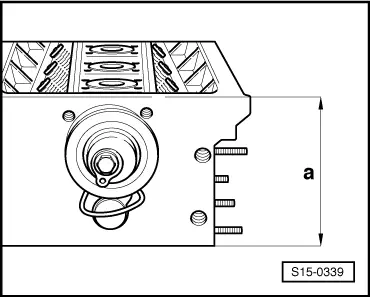
| q | reworking sealing surface → Fig. |
| 26 - | 20 Nm |
| 27 - | Coupling drive tensioning pulley |
| q | check → Chapter |
| q | Tensioning toothed belt → Chapter |
| 28 - | Screw plug, 45 Nm |
| q | install with sealant -D 154 102 A1- |
| q | must not be screwed in too deep |
| q | maximum permissible countersink of the camshaft housing contact surface: 2 mm |
| 29 - | Camshafts |
| q | Inspecting axial play → Fig. |
| q | oil before assembly |
| q | after installation replace gasket rings → Chapter |
| 30 - | O-ring |
| q | replace |
| q | moisten with oil before inserting |
|
|
 Note
Note
|
|
| Dimension | Inlet valve | Exhaust valve | |
| Ø a | mm | 29,5 | 26,0 |
| Ø b | mm | 5,973 | 5,953 |
| c | mm | 100,9 | 100,5 |
| α | ∠° | 45 | 45 |
|
|