
Fabia Mk1
 Note
Note
|
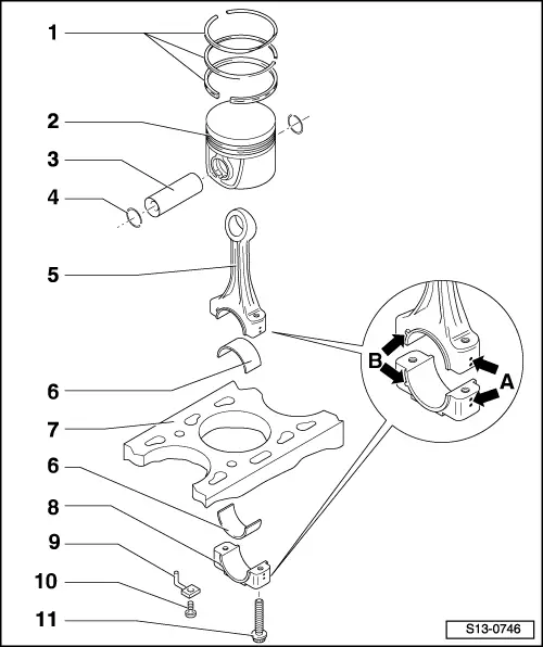
| 1 - | Piston rings |
| q | Offset joint 120° |
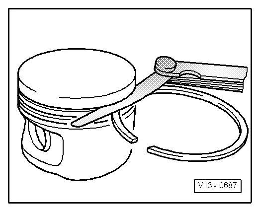
| q | use piston ring pliers for removing and installing |
| q | Marking „TOP“ faces up |
| q | Inspect gap clearance → Fig. |
| q | Inspect end clearance → Fig. |
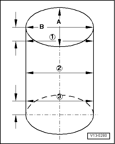
| 2 - | Piston |
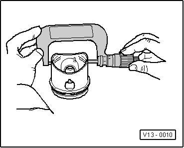
| q | check → Fig. |
| q | mark installation position and matching cylinder |
| q | arrow on piston crown faces towards the belt pulley side |
| q | use piston ring tensioning strap for installing |
| q | Ø Piston: 82.465 mm |
| 3 - | Piston pin |
| q | if stiff, heat piston to 60°C |
| q | with drift -VW 222 A- removing and installing |
| 4 - | Circlip |
| q | replace |
| 5 - | Conrod |
| q | with a split bearing cap |
| q | with oil drilling for lubricating piston pin |
| q | always replace as a set → Electronic Catalogue of Original Parts |
| q | Mark assignment to cylinder -arrow A- |
| q | Fitting position: Marking -arrow B- points towards the belt pulley side |
| q | Axial play when new: 0.10...0.35 mm, wear limit: 0.4 mm |
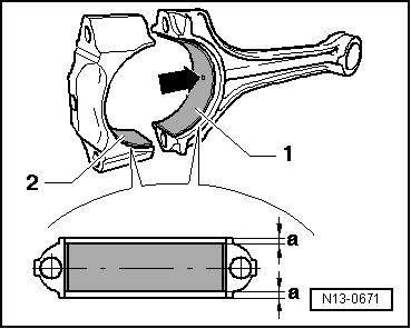
| 6 - | Bearing shell |
| q | pay attention to different versions → Electronic Catalogue of Original Parts. |
| q | at top with oil drilling for piston pin lubrication |
| q | check fitting position → Fig. |
| q | do not mix up used bearing shells (mark) |
| q | ensure tightly located in retaining lugs |
| 7 - | Cylinder block |
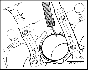
| q | inspect cylinder bore → Fig. |
| q | Ø Cylinder: 82.51 mm |
| 8 - | Conrod bearing cap |
| q | as a result of the conrods separated in the cracking process, the cover fits only in one position |
| q | Mark assignment to cylinder -arrow A- |
| q | Fitting position: Marking -arrow B- points towards the belt pulley side |
| 9 - | Oil injection nozzle |
| q | for piston cooling |
| q | delivered together with Pos. 10 |
| 10 - | Pressure valve, 27 Nm |
| q | opens at a pressure of 0.13...0.16 MPa (1.3...1.6 bar) |
| q | delivered together with Pos. 9 |
| q | install without sealant |
| 11 - | 30 Nm + torque a further 90° (1/4 turn) |
| q | replace → Electronic Catalogue of Original Parts |
| q | Oil thread and contact surface |
| Piston ring | Gap clearance | ||
| new | Wear limit | ||
| Compression rings | mm | 0,20...0,40 | 0,80 |
| Oil scraper ring | mm | 0,25...0,50 | 0,80 |
|
|
| Piston ring | End clearance | ||
| new | Wear limit | ||
| Compression ring | mm | 0,06...0,09 | 0,20 |
| Oil scraper ring | mm | 0,03...0,06 | 0,15 |
|
|
|
|
Note
|
|