skoda Workshop Repair Guides

Skoda Workshop Service and Repair Manuals

Vehicle voltage control unit > < Multi-plug connector on the partition panel (Variant 1)
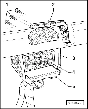
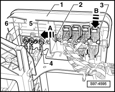
Multi-plug connector on the partition panel (Variant 2)
The multi-plug connector is positioned in the partition wall (front wall) on the left behind the dash panel.
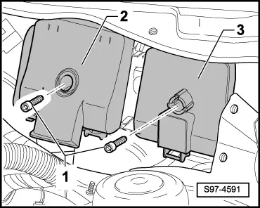
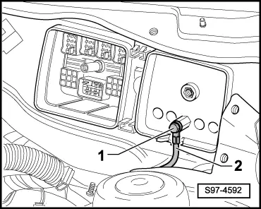
Both partition wall connectors are located on the engine side behind the windscreen wiper motor.
Contact assignment → Current flow diagrams and Fitting locations
  Note
In order to remove the multi-plug connector, first of all the partition wall connector on the engine side must be removed.
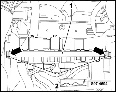
Remove the partition wall connector on the engine side
–  Disconnect earth strap of the battery → Chapter.
–  Removing wiper motor with linkage → Chapter.
   
–  Release screws -1-.
–  Detach partition wall connector -2- and -3- from multi-pin connector.
  S97-4591
–  Release screw -1- and remove the cable -2-.
Remove multi-plug connector on the dash panel side.
–  Removing the dash panel → Body Work; Rep. Gr.70.
  S97-4592
–  Remove vehicle voltage control unit -5- → Chapter.
–  Pull the relay carrier -4- out of the relay carrier support -3- as far as there is enough cable lengths.
  S97-4593
–  To this end unclip the catch pegs -arrows- of the relay carrier -1-.
  S97-4594
–  Release screws -1-.
–  Swivel out the relay carrier support -3- with the multi-plug connector -2- from the partition wall.
  S97-4593
–  Insert the securing lock -2- of the connectors -3- in -the direction of arrow A- into the position “OPEN” (opened).
–  The connectors -3- can be unlocked by pressing on the top catch peg -in the direction of arrow B- and unplugged.
  Note
The number of connectors as well as the cables to the voltage distributor depends on the vehicle equipment.
–  Unscrew the nuts -4- and remove the cables from the voltage distributor -5-.
–  Separate the multi-plug connector -1- from the relay carrier mount -6-.
Install multi-plug connector and partition wall connector
The installation of the multi-plug connector as well as the partition wall connector occurs in reverse order. Pay attention to the following:
  S97-4595
–  Make sure that the relay carrier support -6- and the multi-plug connector -1- are correctly interlocked.
–  Connect the cables to the voltage distributor -5- and the connector -3- to the multi-pin connector → Current flow diagrams and Fitting locations.
–  The securing lock -2- at the multi-plug connector can only be put into the position “CLOSED”, if all the connectors -3- are correctly fitted on.
Tightening torques
  S97-4595
Cable on engine side to multi-plug connector7 Nm
Cables to voltage distributor7 Nm
Relay carrier support to central pipe/dash panel4 Nm
Partition wall connector to multi-plug connector7 Nm


Vehicle voltage control unit > < Multi-plug connector on the partition panel (Variant 1)