
Fabia Mk2
 Note
Note| t | Before installing heat the inner ring of the tapered-roller bearing to 100°C. |
| t | Replace both tapered-roller bearings together. |
| t | Removing and installing differential gear → Chapter. |
| t | When replacing the tapered-roller bearings, the differential housing, the gearbox housing or the clutch housing, set the differential gear → Chapter. |

| 1 - | Gearbox housing |
| 2 - | Adjusting washer |
| q | for the differential gear |
| q | Determine thickness → Chapter |
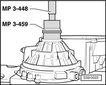
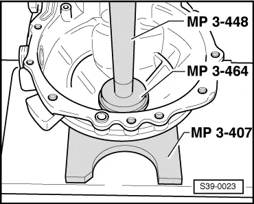
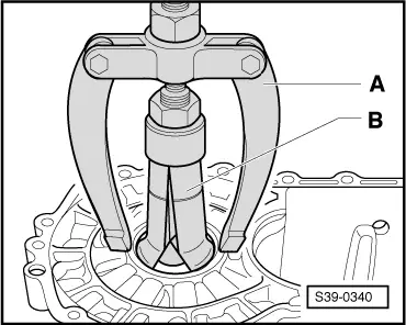
| 3 - | Outer ring/tapered-roller bearing |
| q | removing → Fig. |
| q | installing → Fig. |
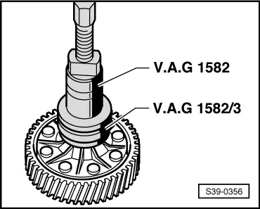
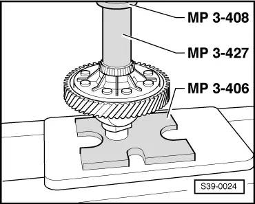
| 4 - | Inner ring/tapered-roller bearing |
| q | remove → Fig. |
| q | pressing on → Fig. |
| 5 - | Differential gear housing |
| q | with gear pinion for final drive |
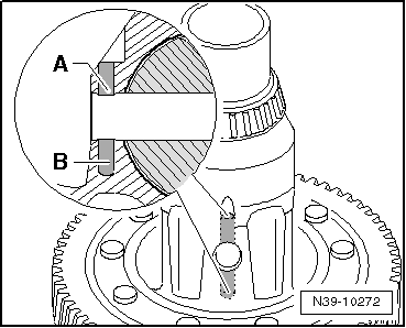
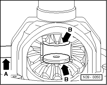
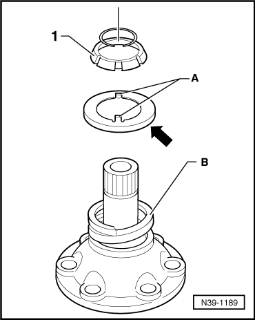
| q | The hole of the tensioning sleeve is adapted to the length of the tensioning sleeve → Fig. |
| q | Assignment → Electronic Catalogue of Original Parts |
| 6 - | Drive wheel for speedometer |
| q | if present, place it on the differential gear housing up to the stop before pressing on the inner ring Pos. 7 |
| 7 - | Inner ring/tapered-roller bearing |
| q | remove → Fig. |
| q | pressing on → Fig. |
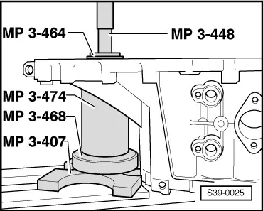
| 8 - | Outer ring/tapered-roller bearing |
| q | pressing out → Fig. |
| q | installing → Fig. |
| 9 - | Clutch housing |
| 10 - | Gasket ring with bushing |
| q | for right flange shaft |
| q | one-piece (a component part) |
| q | replace gasket ring together with bushing in the event of damage to the gasket ring → Chapter |
| 11 - | 25 Nm |
| q | screw to threaded connector Pos. 19 to attach the flange shaft |
| 12 - | Flange shaft |
| q | left - removing and installing → Chapter |
| q | right - removing and installing → Chapter |
| 13 - | Pressure spring for flange shaft |
| q | fitted behind flange shaft |
| 14 - | Thrust washer |
| q | Fitting position: Collar towards pressure spring → Fig. |
| 15 - | Conical ring |
| q | with slots for thrust washer catch |
| q | Fitting position: Cone towards differential gear housing |
| 16 - | Circlip |
| q | holds the conical ring, stop disc and pressure spring in position when the flange shaft is removed |
| 17 - | Stop disc compound |
| q | insert with gear oil |
| 18 - | Large differential bevel gear |
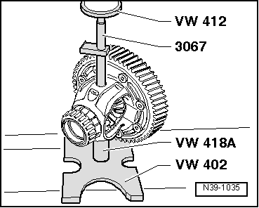
| q | installing → Fig. |
| 19 - | Threaded part |
| q | installing → Fig. |
| 20 - | Differential bevel gear shaft |
| q | remove in combination with short tensioning sleeve → Fig. |
| q | remove in combination with long tensioning sleeve → Fig. |
| q | installing → Fig. |
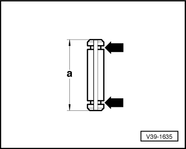
| 21 - | Tensioning sleeve |
| q | to secure the differential bevel gear shaft |
| q | Tensioning sleeves having different lengths are mounted |
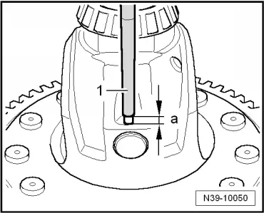
| q | Difference between the tensioning sleeves → Fig. |
| q | short tensioning sleeve: removing and installing → Fig. |
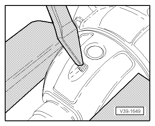
| q | long tensioning sleeve: is cut when removing → Fig. |
| q | long tensioning sleeve: installing → Fig. |
| 22 - | Small differential bevel gear |
| q | installing → Fig. |
| 23 - | Sealing ring |
| q | for left flange shaft |
| q | replace with installed gearbox → Chapter |
|
|
|
|
Note
|
|
Note
|
|
|
|
|
|
|
|
| Dimension „a“ (mm) | Distinguishing feature |
| 28.5 (short tensioning sleeve), removing and installing → Fig. | round slot -arrows- |
| 36.0 (long tensioning sleeve), remove → Fig., install → Fig. | no round slot |
|
|
| Bore | Length of tensioning sleeve (mm) |
| -A- | 28.5 (short tensioning sleeve) |
| -A- and -B- | 36.0 (long tensioning sleeve) |
|
|
|
|
|
|
|
|
|
|