
Fabia Mk2
| Electric/electronic components and fitting locations (Fabia II, Roomster, Rapid) |

| 1 - | Automatic gearbox control unit -J217- |
| q | Fitting location and removing and installing → Chapter |
| q | Control unit is checked by self-diagnosis |
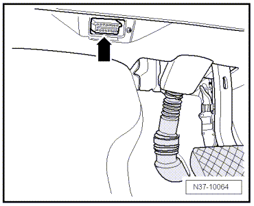
| 2 - | Diagnostic connection |
| q | Fitting location: Cover in driver's footwell → Fig. |
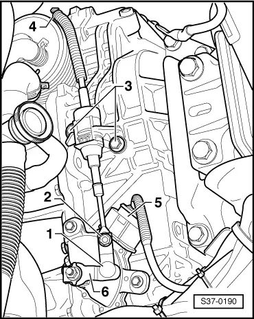
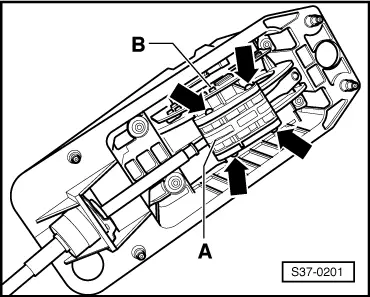
| 3 - | Selector lever lock solenoid -N110- |
| q | Fitting location: |
| t | Fabia II and Roomster up to 10.11 → Fig. |
| t | Fabia II and Roomster as of 11.11 and Rapid → Fig. |
| q | remove and install (Fabia II, Roomster, Rapid) → Chapter |
| q | is checked by self-diagnosis |
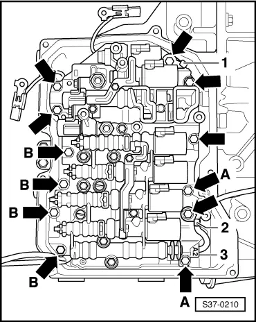
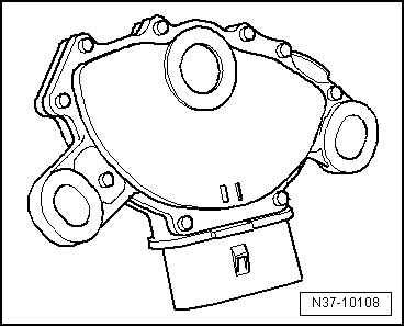
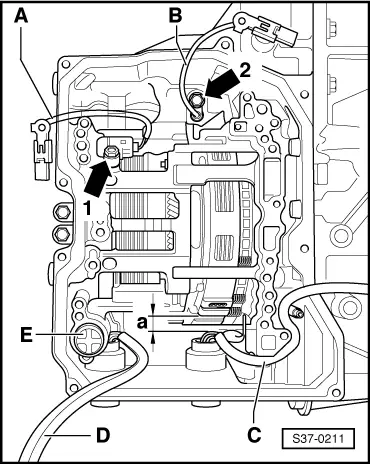
| 4 - | Slide valve body |
| q | Fitting location → Fig. |
| q | removing and installing → Chapter |
| q | Marking of solenoid valves → Chapter |
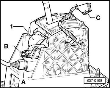
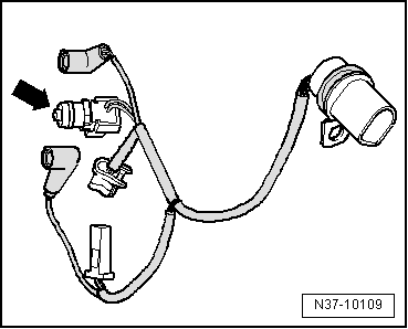
| 5 - | Wiring loom with 8-pin plug and integrated gearbox oil temperature sender -G93- |
| q | Fitting location: Wiring loom is fixed to the slide valve body. → Fig. |
| q | Gearbox oil temperature sender -G93- is checked by self-diagnosis |
| q | removing and installing → Chapter |
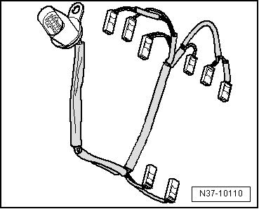
| 6 - | Wiring loom with 14-pin plug |
| q | for solenoid valves and gearbox sensors |
| q | Fitting location: Wiring loom is fixed to the slide valve body. → Fig. |
| q | Designation of solenoid valves and wiring loom routing → Chapter |
| q | removing and installing → Chapter |
| 7 - | Multi-function switch -F125- |
| q | Fitting location → Fig. |
| q | is checked by self-diagnosis |
| q | removing and installing → Chapter |
| q | adjust → Chapter |
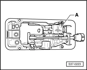
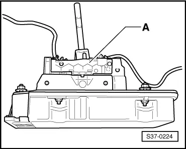
| 8 - | Cover for shift mechanism |
| the shift mechanism of Fabia ll and Roomster is shown in the fig. |
| q | remove and install (Fabia II, Roomster, Rapid) → Chapter |
| q | the Tiptronic switch -F189- is integrated in the shift mechanism; Fitting location: |
| t | Fabia II and Roomster up to 10.11 → Fig. |
| t | Fabia II and Roomster as of 11.11 and Rapid → Fig. |
| 9 - | Relay for starter interlock switch |
| q | Fitting location → Electrical System; Rep. gr.97 |
| 10 - | Gearbox input r.p.m. sender -G182- |
| q | Fitting location → Fig. |
| q | is checked by self-diagnosis |
| q | removing and installing → Chapter |
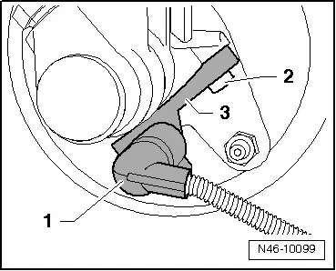
| 11 - | Gearbox output r.p.m. sender -G195- |
| q | Fitting location → Fig. |
| q | is checked by self-diagnosis |
| q | removing and installing → Chapter |
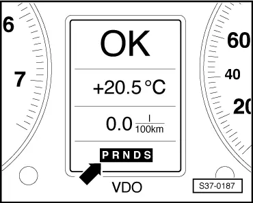
| 12 - | Selector lever position indicator -Y6- |
| q | Fitting location → Fig. |
| q | a switched off gear display points to an emergency operation with deactivated gearbox control unit |
| q | a fully lit gear display points to an emergency operation with activated gearbox control unit |
| q | removing and installing → Electrical System; Rep. gr.90 |
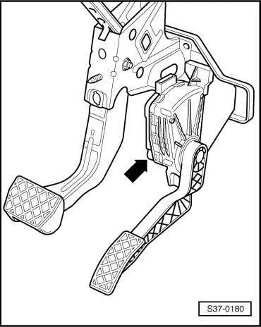
| 13 - | Kick-down switch -F8- |
| q | Fitting location → Fig. |
| q | is checked by self-diagnosis |
| q | Signal transfer from engine to gearbox control unit via CAN databus |
| q | removing and installing accelerator pedal module → Engine; Rep. gr.20 |
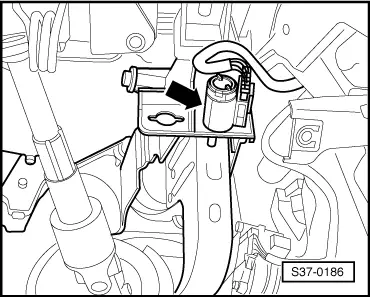
| 14 - | Brake light switch -F- |
| q | Fitting location up to 05.10 → Fig. |
| q | Fitting location as of 06.10 → Fig. |
| q | Signal transfer from engine to gearbox control unit via CAN databus |
| q | is checked by self-diagnosis |
| q | removing and installing → Chassis; Rep. gr.46 |
|
|
|
|
|
|
|
|
|
|
|
|
|
|
|
|
|
|
|
|
|
|
 Note
Note
|
|
|
|
Note
|
|
|
|