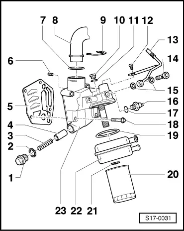
| Disassembling and assembling oil filter holder |
| –
| for pressure relief valve approx. 0.4 MPa (4 bar) |
| –
| for pressure relief valve approx. 0.4 MPa (4 bar) |
| –
| integrated into the oil filter holder |
| –
| push onto tube as far as the collar -Pos. 8- |
| –
| cut open if leaking and replace |
| –
| to exhaust turbocharger |
| 14 - | Hollow screw - 30 Nm |
| 16 - | 0.14 MPa (1.4 bar) oil pressure switch - F1-, 25 Nm |
| –
| cut open if leaking and replace |
| 18 - | 15 Nm + torque a further 1/4 turn (90°) |
| –
| fit into the grooves on the oil cooler |
| –
| slacken with tensioning strap |
| –
| pay attention to installation instructions on oil filter |
| –
| pay attention to change intervals |
| –
| ensure clearance to surrounding components |
| –
| Coat the contact surfaces outside the gasket ring with -AMV 188 001 02 - |
| –
| connection diagram for coolant hoses → Chapter |
| –
| with pressure relief valve approx. 0.4 MPa (4 bar) |
| if leakage is present in the connecting area of the oil feed line at the oil filter holder, in this case replace: the complete holder, oil line, hollow screw and gasket rings |
|
|
|
