
Octavia Mk1
| Connecting diagram for charge pressure control |
 Note
Note| There are different types of non-return valves. If they are not marked by colour, the cone connection corresponds to the dark side. |
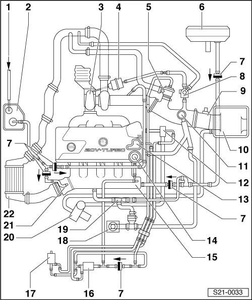
| 1 - | from fuel tank |
| 2 - | Activated charcoal filter |
| q | with activated charcoal filter solenoid valve 1 -N80- |
| 3 - | Exhaust gas turbocharger |
| q | Test charge pressure → Chapter |
| 4 - | Charge pressure control valve pressure unit |
| q | check → Chapter |
| 5 - | Mechanical divert air valve |
| q | check → Chapter |
| 6 - | Brake servo unit |
| 7 - | Non-return valve |
| q | Fitting position (bright/dark side): as shown; the -arrow- points in the flow direction |
| 8 - | Solenoid valve for charge pressure control -N75 - |
| q | test → 1.8 ltr./132 kW Engine, Fuel Injection and Ignition System → Rep. Gr.24 |
| 9 - | Air mass meter -G70- |
| 10 - | Air filter |
| 11 - | Crankcase ventilation pressure control valve |
| 12 - | Combination valve for secondary air |
| 13 - | Vacuum reservoir |
| q | screwed onto the cylinder head cover |
| 14 - | Fuel pressure regulator |
| 15 - | Intake manifold |
| q | with intake air temperature sender -G42- |
| 16 - | Turbocharger divert air valve -N249- |
| q | test → 1.8 ltr./132 kW Engine, Fuel Injection and Ignition System → Rep. Gr.24 |
| 17 - | Secondary air injection valve -N112- |
| q | check → Chapter |
| 18 - | Crankcase ventilation |
| 19 - | Suction spray pump |
| 20 - | Secondary air pump motor -V101- |
| 21 - | Throttle valve control unit -J338- |
| 22 - | Charge air cooler |
| q | with charge pressure sender -G31- |