skoda Workshop Repair Guides

Skoda Workshop Service and Repair Manuals

Check engine speed adaptation by switching on the air conditioning system > < Testing auxiliary signals
Inspecting AC compressor disconnection
  Note
t  The AC compressor signal transmits to the engine control unit the information that the compressor will be switched on within 140 ms.
t  The engine control unit has the possibility to switch off the AC compressor via the same wiring.
t  The deactivation of the AC compressor is performed by the engine control unit:
t  when accelerating rapidly (full load)
t  in emergency operation programme (emergency driving)
t  if the coolant temperature is higher than 120°C
Special tools and workshop equipment required
t  Vehicle system tester -V.A.G 1552- with cable -V.A.G 1551/3-
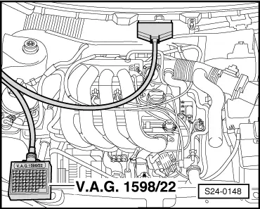
t  Test box -V.A.G 1598/22-
t  Hand multimeter -V.A.G 1526 A- or multimeter -V.A.G 1715-
t  Voltage tester, e.g. - V.A.G 1527-
t  Measuring tool set -V.A.G 1594 A-
t  Current flow diagram
Test conditions
l  Function of the air conditioning system OK
l  No fault in fault memory of the engine control unit.
l  Interior temperature higher than +15°C.
–  Connect vehicle system tester -V.A.G 1552- with cable -V.A.G 1551/3- → Chapter.
–  Start engine.
–  Select “Read measured value block” (function 08) and display group 025 → Chapter.
   
Readout on display:
–  Air conditioning switched off.
Specification in display field 4: Compr. OFF.
–  Switch on air conditioning with the button “Auto”. The compressor must run.
Specification in display field 3: A/C - Hiqh
Specification in display field 4: Compr. ON.
–  Push the accelerator pedal down sharply and release (brief blip throttle).
When pushing the accelerator pedal down rapidly, the read out in the display field 4 must jump for a few seconds from “ON” to “OFF” (compressor shut-off during vehicle acceleration).
 
Reading measured value block         20   ->
1           2            3             4
–  If the readout in the display is not as described, switch off the engine and connect the test box -V.A.G 1598/22 - at wiring loom to the engine control unit.
–  Test the wiring of contact 8 of engine control unit to contact 3 of 10-pin plug for the radiator fan control unit -J293- according to the current flow diagram for short circuit to earth and to positive and/or for open circuit → Current Flow Diagrams, Electrical Fault Finding, Fitting Locations.
–  If there is no fault in the wiring, replace radiator fan control unit -J293- → Heating and Air conditioning system; Rep. Gr.87.
  S24-0148

Check engine speed adaptation by switching on the air conditioning system > < Testing auxiliary signals