skoda Workshop Repair Guides

Skoda Workshop Service and Repair Manuals

Check selector lever position of the automatic gearbox > < Inspecting AC compressor disconnection
Check engine speed adaptation by switching on the air conditioning system
  Note
t  A positive signal is applied to contact 10 at the engine control unit by switching on the air conditioning system.
t  The signal ensures the engine control unit maintains the idling at a constant speed given power supply requirement differences in the air conditioning system.
Special tools and workshop equipment required
t  Vehicle system tester -V.A.G 1552- with cable -V.A.G 1551/3-
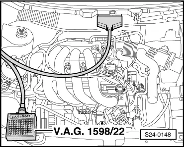
t  Test box -V.A.G 1598/22-
t  Handheld multimeter (e.g. -V.A.G 1526 A-)
t  Voltage tester (e.g. - V.A.G 1527-)
t  Measuring tool set (e.g. -V.A.G 1594 A-)
t  Current flow diagram
Test conditions
l  Function of the air conditioning system OK
l  No fault in fault memory of the air conditioning system.
l  Interior temperature higher than +15°C.
–  Connect vehicle system tester -V.A.G 1552- with cable -V.A.G 1551/3- → Chapter.
–  Start the engine (operating temperature).
–  Switch off the rear window heater.
–  Select Read measured value block (function 08) and display group 020.
   
Readout on display:
Display field 1: Idling speed
Display field 3: Signal from the air conditioning system.
Display field 4: Signal from AC compressor
–  Switch on air conditioning with the button “Auto”. The compressor must run.
Specification in display field 4: “Compr. ON”
Apart from a momentary engine speed reduction (less than a second), the idling speed must remain constant.
If the speed is not maintained constant, check if the signal of the air conditioning system arrives at the engine control unit.
Specification in display field 3: “A/C-High”
Specification in display field 4: “Compr. ON”
 
Reading measured value block         20   ->
800 rpm   neutral   A/C-Low    Compr.OFF
–  If the signal does not arrive, switch off the engine and connect the test box -V.A.G 1598/22- at wiring loom to the engine control unit.
–  Test the wiring of contact 8 of engine control unit to contact 3 of 10-pin plug for the radiator fan control unit -J293- according to the current flow diagram for short circuit to earth and to positive and/or for open circuit → Current Flow Diagrams, Electrical Fault Finding, Fitting Locations.
–  If there is no fault in the wiring, replace radiator fan control unit -J293- → Heating and Air conditioning system; Rep. Gr.87.
  S24-0148

Check selector lever position of the automatic gearbox > < Inspecting AC compressor disconnection