skoda Workshop Repair Guides

Skoda Workshop Service and Repair Manuals

Securing the engine to the assembly stand > < Removing and installing engine
Removing
Removing
  Note
t  
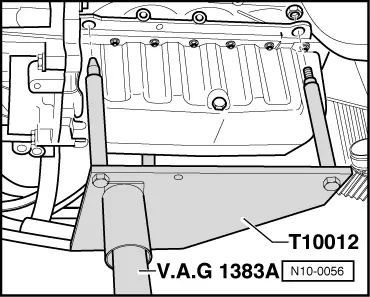
The engine is removed downwards together with the gearbox.
t  All cable straps that have been loosened or cut open when the engine was removed must be fitted again in the same location when it is installed again.
t  
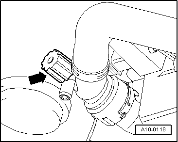
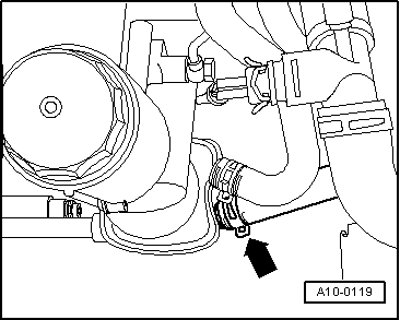
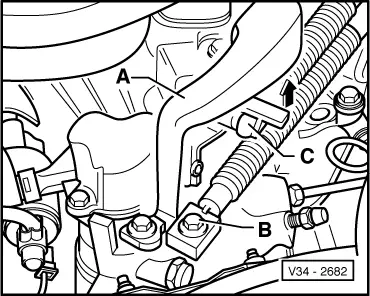
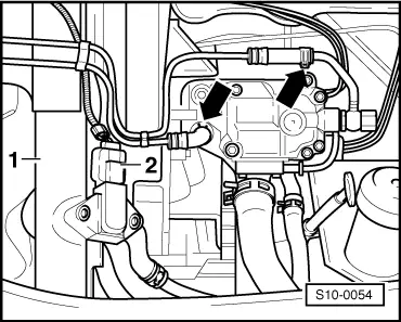
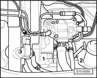
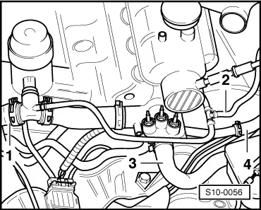
The hose connections are secured with screw-type clips, spring-type clips or clamp-type clips.
t  Always replace clamp-type clips with screw or spring-type clips.
t  
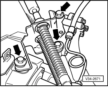
Fuel lines at the engine must only be secured with spring-type clips. The use of clamp-type or screw-type clips is not allowed.
t  Use pliers for spring strap clips to fit the spring strap clips.
t  
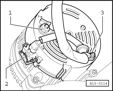
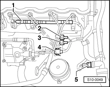
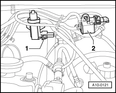
Pay attention to correct assignment of the corresponding connectors, if necessary mark.
Procedure
–  On models fitted with a coded radio set, determine and enter the coding.
–  Switch off the ignition and disconnect the battery earth strap.
   
–  Remove engine cover:
–  Lift off plug -1- and slacken nuts -arrows-.
–  Detach clamp -2- from bolt -3-.
–  Raise vehicle with a lift platform, pay attention to the following points:
  A10-0115
The arms of the lift platform must be positioned under the frame side rail.
  WARNING
Under no circumstances may the arms of the lift platform be positioned under the sills, the front or rear axles.
  S02-0250
Both jacking up points at front are located on both front frame side rails at the height of the marking on the sill.
  WARNING
Never start the engine or engage a gear when the vehicle is raised, while even one driving wheel is still in contact with the ground.
  S02-0251
Both rear jacking up points are located on the rear frame side rails at the height of the marking on the sill.
  S02-0252
–  Remove noise insulation panel in middle as well as on left and right -arrows-.
–  Open the cap of the coolant expansion reservoir.
  A37-0198
–  Turn drain plug -arrow- on the radiator to the left, if necessary fit auxiliary hose onto connection.
  A10-0118
–  In addition, detach coolant hose at bottom of oil cooler -arrow- and allow remaining coolant to drain.
  A10-0119
–  Remove air guide hose -1-.
–  Detach vent hose -3- and unplug connector for air mass meter -2-.
–  Slacken bolts -4- and -5-, remove air filter housing.
  S10-0048
–  Remove battery and battery tray -arrows-.
  A10-0116
–  Unbolt earth strap -1-.
–  Detach cables -3- and -4- at starter.
–  Separate plug connection -2- and pull out of fixture.
–  Detach cables from fixture at starter and lay to the side, unscrew the fixture.
  A37-0195
–  Unbolt terminal -30/B+-, cable -1- at alternator.
–  Detach plug connection -2- of terminal D+.
–  Unscrew cable clamp -3-.
Vehicles with air conditioning
–  Disconnect plug connection from AC compressor.
For all vehicles:
  A10-0114
–  Disconnect wiring/plug:
1 - Edge connector for glow plugs
2 - Plug connection for needle lift sender -G80- (brown, connector black)
3 - Plug connection for engine speed sender -G28- (black)
4 - Plug connection for injection pump
5 - Plug for electronic thermoswitch -F14- (black, only for air conditioning system)
–  Disconnect connector for coolant temperature sender -G62- (black) at cylinder head flange.
–  Disconnect plug for oil pressure switch -F1- at oil filter holder.
–  Detach cable harness for the fixtures and run out to the side.
Vehicles fitted with a manual gearbox
  S10-0049
–  Mark the installed position of the shift cable -B- for the gearbox shift lever.
–  Remove balancing weight -A- and shift cable -B- from shift lever.
–  Detach selector cable from driver/relay lever -C-, to do so raise lug in direction of arrow.
–  Unclip hose line of the slave cylinder at cable support.
  V34-2682
–  Disconnect cable support from gearbox and lay aside -arrow-.
  V34-2671
–  Remove the slave cylinder -arrows- and lay aside, secure with wire, do not open the line system.
  Note
Do not depress the clutch pedal.
  S10-0045
–  Unplug following connector:
1 - Speedometer sender -G22-
2 - Reversing light switch -F4-
Vehicles with automatic gearbox
  A34-0016
–  Use screwdriver to press off selector cable -1- at gearbox selector lever -4- and pull off securing clasp -3- at support bearing.
–  Take off selector lever cable and place to the side.
–  Unbolt bracket for pressure line of power-assisted steering at gearbox support.
  A37-0194
–  Disconnect plug.
1 - to the solenoid valves
2 - to speedometer sender -G22-
3 - at the multifunction switch -F125-
4 - on speed sensor -G38-
Continued for all vehicles
  A37-0193
–  Remove fuel hoses -arrows- at the injection pump, close with clean plugs and lay aside.
–  Unplug connector -2- at intake manifold temperature sender -G72- with intake manifold pressure sender -G71-.
–  Remove air guide pipe -1-.
–  Remove following coolant hoses with pliers for spring strap clips:
  S10-0054
1 - Coolant hose at bottom of coolant regulator housing and radiator (remove hose).
2 - Coolant hose to the expansion reservoir.
  S10-0055
1 - Top coolant hose at branch piece
2 - Slacken coolant hose to the expansion reservoir and heat exchanger from cylinder head
3 - Coolant hose to the heat exchanger
4 - Coolant hose from heat exchanger at coolant pipe
–  Detach vacuum hose:
–  on the vacuum pump
–  on the mechanical exhaust gas recirculation valve
  S10-0056
–  Unplug connector -1- on the exhaust gas recirculation valve -N18-.
–  Release plug connection from the solenoid valve for charge air pressure limitation -N75--2-.
–  Detach charge pressure control solenoid valve -N75--2- from holder and place onto the engine (hoses should remain connected up, they must be released from the fixtures).
–  Disconnect plug from change-over valve for intake manifold flap -N239-.
–  Disconnect vacuum hose from change-over valve for intake manifold flap.
–  Remove the air guide pipe between the charge air cooler and exhaust turbocharger → Chapter.
  Note
Mark the rotation direction before removing the V-ribbed belt. Reversing the rotation direction of an already used belt may destroy it. Pay attention to the correct position of the V-ribbed belt in the belt pulley when installing it.
–  Position flat ring spanner SW 16 at hexagon of tensioning pulley.
  A10-0121
–  Swing the the tensioning pulley in the direction of the arrow detension the V-ribbed belt.
–  Remove the V-ribbed belt.
  A10-0122
–  Unscrew 3 brackets for the pressure line of power-assisted steering -arrows-.
–  Remove belt pulley of hydraulic pump for power-assisted steering.
–  Unscrew vane pump of the power-assisted steering and tie up to the body. The lines on the vane pump remain connected up.
Vehicles with air conditioning
  WARNING
Do not open the refrigerant circuit of the air conditioning system.
  S10-0057
–  Remove AC compressor and tie up together with the connected hoses with wire to the towing lug -arrow-.
  Note
Protect the shock absorber with suitable adhesive tape from scratches.
For all vehicles
  A10-0124
–  Remove pendulum support -arrows-.
–  Unscrew the drive shafts from the gearbox flange and attach with wire to body.
Vehicles with increased cooling
–  Remove right electric fan (smaller fan wheel diameter) → Chapter.
For all vehicles
–  Remove front part of exhaust system → Chapter.
  A37-0200
–  Screw engine mount -T10012- to the cylinder block with fixing nut and bolt M10 to 40 Nm.
–  Slightly raise the engine and gearbox with the engine/gearbox jack.
  Note
Use the double ladder (e.g. V.A.S -5085-) to remove the fixing screws of the engine and gearbox console.
  N10-0056
–  Unscrew screws from the engine console -arrows-.
  A10-0125
–  Unscrew screws from the gearbox console -arrows-.
–  Carefully lower the engine with gearbox.
  Note
When lowering, the assembly block must be guided by a second mechanic, in order to avoid damage to the body due to the low clearance. At the same time make sure the drive shaft boots are not damaged.
Vehicles with automatic gearbox
–  Detach coolant hoses at ATF radiator.
–  Pull off plug in hole of torque converter cover plate.
  A10-0126
–  Unscrew 3 nuts -arrow- from torque converter, rotate crankshaft each time 1/3 revolution for this step.
–  After separating the engine from the gearbox, secure the torque converter against dropping down.
Continued for all vehicles
–  Remove engine/gearbox connecting screws.
–  Separate gearbox from engine.
  A37-0201

Securing the engine to the assembly stand > < Removing and installing engine