| –
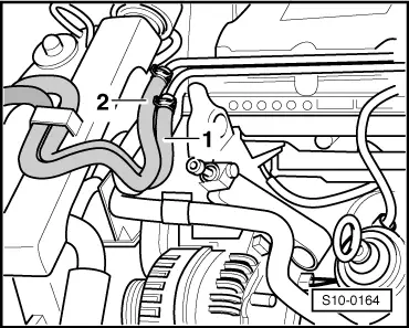
| Disconnect the fuel-intake hose -1- and the fuel-return hose -2- from the pipes. |
| –
| Remove pipe at top and the charge air connection pipe → Chapter. |
| –
| Remove bracket for power-assisted steering pipe. |
| –
| Remove power steering fluid reservoir, do not detach hoses, and place down to the side. |
| –
| Pull off the coolant hoses for expansion reservoir from the pipes at the engine and the coolant hose at the bottom from the cooler → Chapter. |

Note | After the hoses are separated, remaining coolant may flow out; place the drip tray below for this purpose. |
| –
| Remove the valve holder -N18- and -N75- above the brake servo unit. Disconnect the plug connector and electrical lines for each part. |
| –
| Detach coolant hose from connection fitting of cylinder head. |
| –
| Detach coolant hoses to the heat exchanger. |
| –
| Remove vacuum hose from the brake servo unit. |
| For vehicles fitted with optional equipment |
| –
| Separate connector for glow plugs of the coolant heater (glow plugs are located next to the tandem pump in left of engine compartment). |
| Continued for all vehicles |
| –
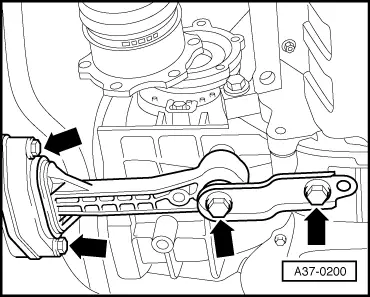
| Unbolt PAS pipe from engine and gearbox. |
| –
| Disconnect earth strap from the vehicle body. |
| –
| Disconnect the following plug connections: |
| t
| Starter plug connection |
| t
| Plug connection for alternator |
| t
| Plug connection of reversing light switch |
| t
| Plug connection for AC compressor (only on vehicles with air conditioning) |
| –
| Separate electric cable from alternator. |
Note | The assembly is removed together with the cable harness. |
| –
| Unplug connector of engine control unit, unclip wiring harness from the supports in the water channel. |
| –
| Open engine wiring harness cover in left of engine compartment. |
| –
| Unclip wiring harness from the cover. |
| –
| Take connector for main engine wiring harness together with secondary engine wiring harness out of the fixture in left of engine compartment and disconnect. |
| –
| Separate + cable from starter. |
| –
| Unclip wiring harness from supports, separate plug connections (if fitted) and suspend freely at engine. |
|
|
|
 WARNING