Skoda Workshop Service and Repair Manuals
HOME
FEATURES
MENU
INDEX
ABOUT US
Test control unit input sizes >
< Test air mass meter G70
Octavia Mk1
Drive unit
1.9 ltr./66 kW (TDI) Engine, Fuel Injection and Glow Plug System
Fuel preparation system Diesel injection
Inspecting the exhaust gas recirculation system
Piping diagram for exhaust gas recirculation
Piping diagram for exhaust gas recirculation
Piping diagram for exhaust gas recirculation
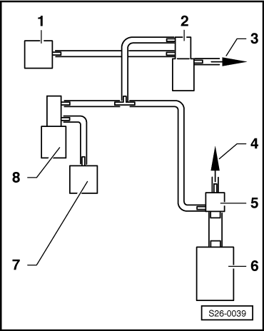
For vehicles ? 07.00
1 -
Mechanical exhaust gas recirculation valve
2 -
Exhaust gas return valve -N18-
3 -
To air filter
4 -
To the brake servo unit
5 -
Non-return valve
6 -
Vacuum pump
7 -
Vacuum setting element for intake manifold flap
–
for vehicles 08.97 ?
8 -
Changeover valve for intake manifold flap -N239-
–
for vehicles 08.97 ?
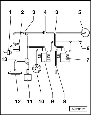
For vehicles 08.00 ?
1 -
Vacuum setting element for intake manifold flap
2 -
Changeover valve for intake manifold flap -N239-
3 -
Distributor part
4 -
Non-return valve
–
white connection points to charge pressure control solenoid valve -N75-
5 -
Vacuum unit
6 -
To air filter
7 -
Solenoid valve for charge pressure control -N75-
8 -
Vacuum setting element
–
for the charge pressure control valve
–
Components of the exhaust gas turbocharger cannot be replaced individually
9 -
Exhaust gas return valve -N18-
10 -
Mechanical exhaust gas recirculation valve
11 -
Vacuum pump
12 -
Brake servo unit
13 -
Non-return valve
Drive unit
1.9 ltr./66 kW (TDI) Engine, Fuel Injection and Glow Plug System
Fuel preparation system Diesel injection
Inspecting the exhaust gas recirculation system
Piping diagram for exhaust gas recirculation
Test control unit input sizes >
< Test air mass meter G70