skoda Workshop Repair Guides

Skoda Workshop Service and Repair Manuals

Piping diagram for exhaust gas recirculation > < Testing exhaust gas recirculation valve N18
Test air mass meter G70
Test air mass meter -G70-
The air mass meter signal is required by the control unit to calculate the allowed injection rate and to control the exhaust gas recirculation. The lower the signal from the air mass meter the less fuel may be injected.
Special tools and workshop equipment required
t  Vehicle system tester -V.A.G 1552- with cable -V.A.G 1551/3, 3A, 3B oder 3C-
t  Handheld multimeter (e.g. -V.A.G 1526 A-)
t  Measuring tool set (e.g. -V.A.G 1594 A-)
t  Test box -V.A.G 1598/22- or -V.A.G 1598/31-
Test conditions
l  Fuses No. 29 and 34 o.k.
Test sequence
–  Read measured value block, display group 010, engine at idling speed → Chapter.
  WARNING
The -V.A.G 1552- should be operated by a second person.
   
–  Observe display in display field 1.
Specified value: 230...370 mg/s
If the specified value is not reached:
–  Inspecting the exhaust gas recirculation system → Chapter.
If the specified value is reached:
–  Accelerate vehicle in 3rd gear at full throttle from about 1500 rpm.
–  At about 3000 rpm read off the value indicated in the display field 4 and note.
 
Reading measured value block 10     ->
309 mg/s   1030 mbar   1011 mbar   0.0 %
–  Specified value in display field 4: 100 % (accelerator pedal position)
If the specified value is not reached:
–  Repeat the test and accelerate vehicle at full throttle.
For vehicles ? 07.97
 
Reading measured value block 10     ->
830 mg/s   1030 mbar   1850 mbar   100 %
Specified value in display field 3: 1700….2150 mbar (charge pressure)
 
Reading measured value block 10     ->
830 mg/s   1030 mbar   1850 mbar   100 %
Specified value in display field 1: >750 mg/s (inducted air mass)
For vehicles 08.97 ?
 
Reading measured value block 10     ->
830 mg/s   1030 mbar   1850 mbar   100 %
Specified value in display field 3: 1750….2050 mbar (charge pressure)
 
Reading measured value block 10     ->
830 mg/s   1030 mbar   1850 mbar   100 %
Specified value in display field 1: >800 mg/s (inducted air mass)
For all vehicles
If the specified value is not reached:
–  Test charge pressure → Chapter.
–  Replace the air mass meter -G70-.
If display field 1 constantly displayed (fixed replacement value):
   for vehicles ? 07.97 = 425 mg/s
   for vehicles 08.97 ? = 550 mg/s.
–  Switch off ignition.
For the test box -V.A.G 1598/22-
For vehicles ? 07.98
 
Reading measured value block 10     ->
830 mg/s   1030 mbar   1850 mbar   100 %
–  Unplug connector from air mass meter -G70-.
–  Switch on ignition.
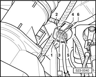
–  Connect the multimeter for voltage measurement to the following contacts of the connector:
  S23-0040
6-pin plug on wiring loom, contactSpecified value
3 + earthapprox. battery voltage
3 + 5approx. battery voltage
1 + earthapprox. 5 V
1 + 5approx. 5 V

If the specified values are not reached:
–  Connect the test box to the wiring loom of the engine control unit → Chapter.
–  Test the wiring, eliminate possible open circuits or short-circuits according to current flow diagram → Current flow diagrams and Fitting locations.
For vehicles 08.98 ?
   
–  Unplug connector from air mass meter -G70-.
–  Switch on ignition.
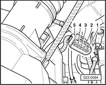
–  Connect the multimeter for voltage measurement to the following contacts of the connector:
  S23-0084
5-pin plug on wiring loom, contactSpecified value
2 + earthapprox. battery voltage
2 + 3approx. battery voltage
4 + earthapprox. 5 V
4 + 3approx. 5 V

If the specified values are not reached:
–  Connect the test box to the wiring loom of the engine control unit → Chapter.
–  Test the wiring, eliminate possible open circuits or short-circuits according to current flow diagram → Current flow diagrams and Fitting locations.
For the test box -V.A.G 1598/31 -
   
–  Unplug connector from air mass meter -G70-.
–  Switch on ignition.
–  Connect the multimeter for voltage measurement to the following contacts of the connector:
  S23-0084
5-pin plug on wiring loom, contactSpecified value
2 + earthapprox. battery voltage
2 + 3approx. battery voltage
4 + earthapprox. 5 V
4 + 3approx. 5 V

If the specified values are not reached:
–  Connect the test box to the wiring loom of the engine control unit → Chapter.
–  Test the wiring, eliminate possible open circuits or short-circuits according to current flow diagram → Current flow diagrams and Fitting locations.
For all vehicles
If the lines are not found to be faulty:
–  Replacing engine control unit -J248- → Chapter.
   

Piping diagram for exhaust gas recirculation > < Testing exhaust gas recirculation valve N18