skoda Workshop Repair Guides

Skoda Workshop Service and Repair Manuals

Testing auxiliary signals > < Test modulating piston movement sender G149 and metering adjuster N146
Check accelerator pedal position sender G79
Check accelerator pedal position sender -G79-
The accelerator pedal position sender is located at the accelerator pedal and transmits the driver's instructions to the engine control unit.
Special tools and workshop equipment required
t  Vehicle system tester -V.A.G 1552- with cable -V.A.G 1551/3, 3A, 3B oder 3C-
t  Handheld multimeter (e.g. -V.A.G 1526 A-)
t  Measuring tool set (e.g. -V.A.G 1594 A-)
t  Test box -V.A.G 1598/22- or -V.A.G 1598/31-
Test sequence
–  Connecting up the vehicle system tester and selecting → Chapter the control unit for engine electronics.
–  Read measured value block, display group 002, engine stoppage.
   
Specified value in display field 2: 0.0% (accelerator pedal not pressed)
 
Reading measured value block 2     ->
0 rpm    0.0 %      0 1 0      18.4 °C
Specified value in display field 3: 0 1 0 (accelerator pedal not pressed)
–  Slowly press the accelerator pedal down.
 
Reading measured value block 2     ->
0 rpm    0.0 %      0 1 0      18.4 °C
Specified value in display field 2: the value must increase up to 100% (when accelerator pedal is fully depressed). Specified value in display field 3: 0 0 0 (accelerator pedal pressed)
If the final nominal value is not reached:
For vehicles ? 07.98
–  Setting accelerator pedal position sender → Chapter.
If the display does not change or changes irregularly:
–  Switch off ignition.
 
Reading measured value block 2     ->
0 rpm    100.0 %      0 0 0      18.4 °C
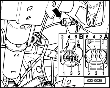
–  Separate plug connection -arrow- for accelerator pedal position sender -G79-.
  S23-0035
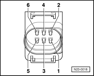
–  Test resistance of accelerator pedal position sender:
  N23-0018
Accelerator pedalContactsSpecified value
not pressed1 + 30.6...1.4 kΩ
not pressed2 + 30.6...1.4 kΩ
not pressed4 + 60.6...1.2 kΩ
pressed∞ Ω
pressed5 + 60.6...1.2 kΩ
not pressed∞ Ω

If the specified value is not reached:
–  Replace accelerator pedal position sender -G79-.
If the specified value is reached:
   
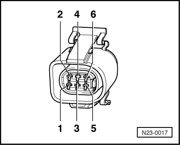
–  Inspect power supply of accelerator pedal position sender:
  N23-0017
6-pin plug on wiring loom,
contact
Specified value
2 + earthapprox. 5 V
2 + 3approx. 5 V
5 + earthapprox. 5 V
5 + 6approx. 5 V

If the specified value is not reached:
–  Connect test box -V.A.G 1598/22- or -V.A.G 1598/31- to wiring loom of engine control unit → Chapter.
–  Check el. wiring, if necessary eliminate open circuits in wiring or short-circuits according to current flow diagrams → Current flow diagrams and Fitting locations.
If the lines are not found to be faulty:
–  Replacing engine control unit -J248- → Chapter.
For vehicles 08.98 ?
–  Remove the trim panel below the dash panel → Body Work → Rep. Gr.68.
–  Unplug the 6 pin plug connection from accelerator pedal position sender -G79-.
   
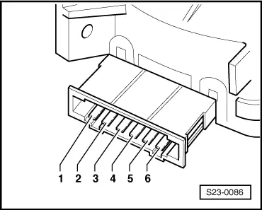
–  Test resistance of accelerator pedal position sender:
  S23-0086
Accelerator pedalContactsSpecified value
not pressed4 + 30.6...1.4 kΩ
not pressed2 + 30.6...1.4 kΩ
not pressed5 + 60.6...1.4 kΩ
pressed∞ Ω
pressed1 + 60.6...1.4 kΩ
not pressed∞ Ω

If the specified value is not reached:
–  Replace accelerator pedal position sender -G79-.
If the specified value is reached:
   
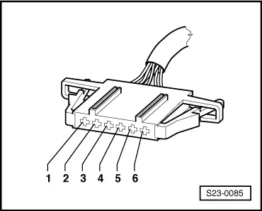
–  Inspect power supply of accelerator pedal position sender:
  S23-0085
6-pin plug on wiring loom, contactSpecified value
2 + earthapprox. 5 V
2 + 3approx. 5 V
1 + earthapprox. 5 V
1 + 6approx. 5 V

If the specified value is not reached:
–  Connect test box -V.A.G 1598/22- or -V.A.G 1598/31- to wiring loom of engine control unit → Chapter.
–  Check el. wiring, if necessary eliminate open circuits in wiring or short-circuits according to current flow diagrams → Current flow diagrams and Fitting locations.
If the lines are not found to be faulty:
–  Replacing engine control unit -J248- → Chapter.
   

Testing auxiliary signals > < Test modulating piston movement sender G149 and metering adjuster N146