skoda Workshop Repair Guides

Skoda Workshop Service and Repair Manuals

Check accelerator pedal position sender G79 > < Test brake light switch and brake pedal switch
Test modulating piston movement sender G149 and metering adjuster N146
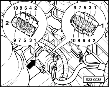
Test modulating piston movement sender -G149- and metering adjuster -N146-
The metering adjuster is an electromagnetic rotary adjuster controlled by the control unit. The eccentric shaft of the metering adjuster moves the modulating piston on the high-pressure piston and this determines the injection rate.
The modulating piston movement sender gives the control unit feedback on the position of the modulating piston and thus determines the volume of the injection rate.
Special tools, test equipment and aids required
t  Vehicle system tester -V.A.G 1552- with cable -V.A.G 1551/3, 3A, 3B oder 3C-
t  Handheld multimeter (e.g. -V.A.G 1526A-)
t  Measuring tool set (e.g. -V.A.G 1594A-)
t  Test box -V.A.G 1598/22- or - V.A.G 1598/31-
Test sequence
–  Connecting up the vehicle system tester and selecting → Chapter the control unit for engine electronics.
–  Read measured value block, display group 001, engine at idling speed → Chapter.
   
–  Check display in display field 4 (coolant temperature).
Specified value: min. 85°C
Only proceed with test once the coolant temperature has been reached.
–  If necessary disconnect all connected auxiliary consumers (air conditioning, rear window heater, light etc.).
–  Test display in display field 3 (voltage from modulating piston movement sender).
For vehicles ? 04.99
 
Reading measured value block 1     ->
900/min    5.6 mg/s    1.480 V   87.3 °C
Specified value: 1.450...1.950 V
For vehicles 05.99 ?
 
Reading measured value block 1     ->
900/min    5.6 mg/s    1.480 V   87.3 °C
Specified value: 1.300...2.100 V
For all vehicles
If the specified value is not reached:
–  Test modulating piston movement sender -G149- → Anchor.
Electrically test modulating piston movement sender -G149- and metering adjuster -N146-
–  Switch off ignition.
 
Reading measured value block 1     ->
900/min    5.6 mg/s    1.720 V   87.3 °C
–  Disconnect the plug connection -arrow- from the injection pump.
–  Connect multimeter for resistance measurement to the following contacts of the connector holder -2-:
  S23-0038
Plug connection for injection pumpSpecified value
1 + 24,9...7,5 Ω
3 + 24,9...7,5 Ω
6 + 50,5...2,5 Ω

If the specified values are not reached:
–  Replacing injection pump → Chapter.
Check supply voltage and cable connections
–  Switch off ignition.
–  Disconnect the plug connector on the injection pump.
–  Switch on ignition.
–  Connect multimeter for voltage measurement to the following contacts of the connector -1- at the wiring loom:
   
10-pin plug on wiring loom,
contact
Specified value
1 + earthapprox. 2.5 V
3 + earthapprox. 2.5 V
5 + earthapprox. battery voltage

If the specified values are not reached:
–  Connect test box -V.A.G 1598/22 - or -V.A.G 1598/31- to wiring loom of engine control unit → Chapter.
   
–  Check el. wiring, if necessary eliminate open circuits in wiring or short-circuits according to current flow diagrams (plug -1-) → Current flow diagrams and Fitting locations.
If the lines are not found to be faulty:
–  Replacing engine control unit - J248- → Chapter.
  S23-0038

Check accelerator pedal position sender G79 > < Test brake light switch and brake pedal switch