| Removing and installing crankshaft |

Note | t
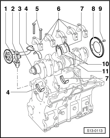
| Before removing the crankshaft, ensure a suitable place is available for placing it down so that the sensor rotor (pos. 8) does not rest against anything or get damaged. |
| t
| Secure the engine with engine mount -MP 1-202- and distance sleeves - T30010- on the assembly stand -MP 9-101 - before performing assembly work. |
Note | t
| For engine with engine code AZJ |
| t
| Before removing the crankshaft, first of all remove the gearbox with balancing shafts → Chapter. |
| –
| for engine with identification characters AEG, APK, AQY and AZH |
| 4 - | Bearing shells 1, 2, 4 and 5 |
| –
| for bearing cap without lubricating groove |
| –
| for cylinder block with lubricating groove |
| –
| used bearing shells must not be mixed up (mark) |
| –
| only use → Fig. bearing shells with the same colour coding when replacing |
| 5 - | 65 Nm + torque a further 90° (1/4 turn) |
| –
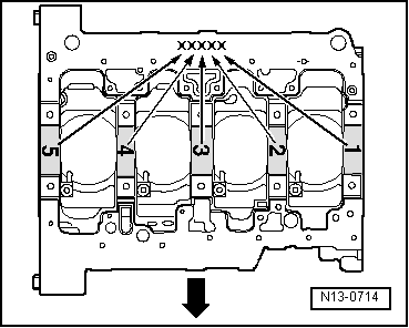
| Bearing cap 1: belt pulley side |
| –
| Bearing cap 3: with recesses for thrust washers |
| –
| retaining lugs of the bearing shells of the cylinder block/bearing cap must be on top of one another |
| –
| for engine speed sender -G28 - |
| –
| assembly only possible in one position -holes offset- |
| 9 - | 10 Nm + torque a further 90° (1/4 turn) |
| –
| for bearing cap and cylinder block, bearing 3 |
| –
| pay attention to the marking |
| –
| pay attention to different version |
| –
| Axial play when new: 0.07…0.23 mm |
| –
| Crankshaft bearing journal: Ø 54.00 mm |
| –
| Conrod bearing journal: Ø 47.80 mm |
|
|
|