| Disassembling and assembling piston and conrod |
| For engine with identification characters AEG, APK, AQY and AZH |

Note | Secure the engine with engine mount -MP 1-202- and distance sleeves - T30010- on the assembly stand -MP 9-101 - before performing assembly work. |
| –
| pay attention to different version |
| –
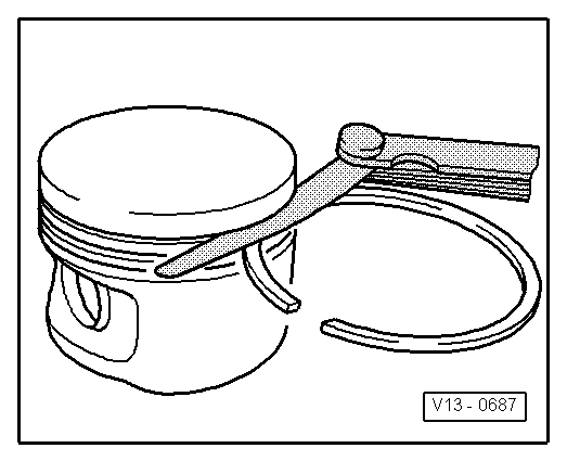
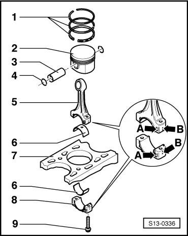
| use piston ring pliers for removing and installing |
| –
| Oil scraper ring 2 part |
| –
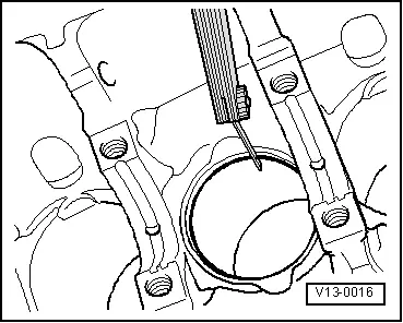
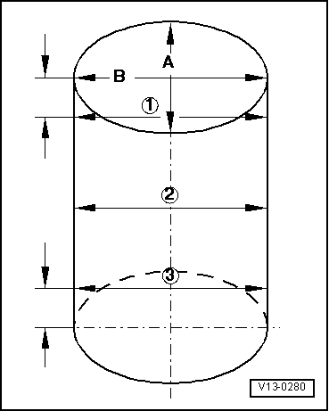
| Inspect gap clearance → Fig. |
| –
| Inspect end clearance → Fig. |
| –
| pay attention to different version |
| –
| mark installation position relative to conrod and mark matching cylinder with felt pen |
| –
| arrow on piston crown faces towards the belt pulley side |
| –
| pay attention to different version |
| –
| mark assignment to cylinder see -arrow B- |
| Markings -arrow A- must be positioned one above the other and point to the belt pulley side |
| –
| with oil drilling for lubricating piston pin |
| –
| pay attention to different version |
| –
| mark assignment to cylinder see -arrow B- |
| Markings -arrow A- must be positioned one above the other and point to the belt pulley side |
| 5 - | 30 Nm + torque a further 90° (1/4 turn) |
| –
| oil thread and head contact surface |
| 6 - | Pressure relief valve, 27 Nm |
| 0.25…0.32 MPa (2.5...3.2 bar) overpressure |
| –
| replace without sealant |
| –
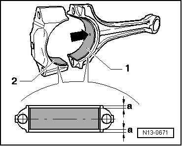
| do not mix up used bearing shells (mark) |
| –
| ensure tightly located in retaining lugs |
| –
| Axial play when new: 0.10...0.35 mm, wear limit: 0.4 mm |
| –
| with oil drilling for lubricating piston pin |
| –
| pay attention to different version |
| –
| inspect cylinder bore → Fig. |
| –
| replace together with nut Pos. 5 |
| –
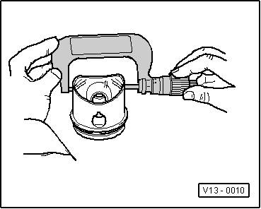
| if stiff, heat piston to 60°C |
| –
| with drift -VW 222 A- removing and installing |
| For engine with engine code AZJ |
Note | Secure the engine with engine mount -MP 1-202- and distance sleeves - T30010- on the assembly stand -MP 9-101 - before performing assembly work. |
| –
| use piston ring pliers for removing and installing |
| –
| Oil scraper ring 2 part |
| –
| Inspect gap clearance → Fig. |
| –
| Inspect end clearance → Fig. |
| –
| mark installation position relative to conrod and mark matching cylinder with felt pen |
| –
| arrow on piston crown faces towards the belt pulley side |
| –
| if stiff, heat piston to 60°C |
| –
| with drift -VW 222 A- removing and installing |
| –
| always replace as a set only |
| –
| mark assignment to cylinder see -arrow B- |
| –
| Fitting location: Markings -arrow A- must be positioned one above the other and point to the belt pulley side |
| –
| check fitting position → Fig. |
| –
| do not mix up used bearing shells (mark) |
| –
| insert bearing shells in the centre |
| –
| Axial play when new: 0.10...0.35 mm, wear limit: 0.4 mm |
| –
| inspect cylinder bore → Fig. |
| –
| mark assignment to cylinder see -arrow B- |
| 9 - | 30 Nm + torque a further 90° (1/4 turn) |
| –
| oil thread and head contact surface |
|
|
|