
Octavia Mk1
| Electrical and electronic components - fitting positions |

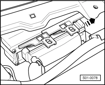
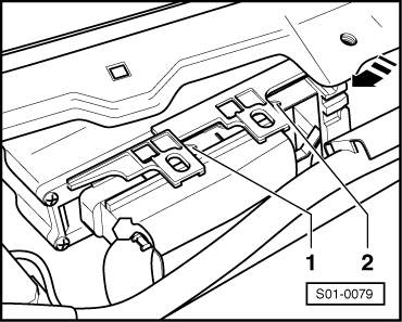
| 1 - | Automatic gearbox control unit -J217- |
| q | Fitting position: in right of plenum chamber |
| q | removing and installing → Anchor |
| q | is checked by self-diagnosis → Chapter |
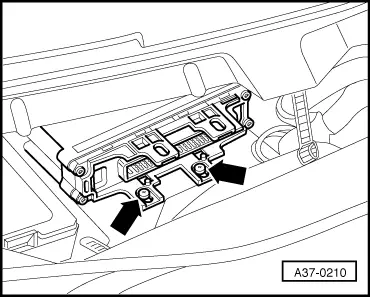
| 2 - | Engine control unit |
| q | Fitting position: at center of plenum chamber |
| q | removing and installing: → Engine → Rep. Gr.23 or → Rep. Gr.24 |
 Note
Note| If the engine or gearbox control units are replaced, the system must be put into the basic setting → Chapter. |
| 3 - | Diagnostic connection |
| q | Fitting position: in the storage area below the steering column |
| 4 - | Slide valve body |
| q | Fitting position: under the gearbox oil pan |
| q | removing and installing → Chapter |
| q | the solenoid valves are fixed to the slide valve body -N88-, -N89-, -N90-, -N91-, -N92-, -N93- and -N94- |
| q | Components are checked by the self-diagnosis |
| q | after replacing, perform basic setting → Chapter |
| 5 - | Conductor foil with integrated gearbox oil temperature sender -G93- |
| q | Fitting position: In the oil pan under the slide valve body |
| q | removing and installing → Chapter |
| q | Do not bend, buckle or damage in any way the conductor foil |
| q | The gearbox oil temperature sender -G93- is checked by the self-diagnosis |
| 6 - | Multi-function switch -F125- |
| q | Fitting position: At the right of the gearbox |
| q | removing and installing → Chapter |
| q | is checked by self-diagnosis |
| 7 - | Gearbox speed sender -G38- |
| q | Fitting position: At the right of the gearbox |
| q | removing and installing → Chapter |
| q | is checked by self-diagnosis |
| 8 - | Vehicle speed sender -G68- |
| q | Fitting position: At the top of the gearbox, covered by the gearbox support |
| q | removing and installing → Chapter |
| q | is checked by self-diagnosis |
| 9 - | Throttle valve control unit -J338- |
| q | removing and installing: → Engine → Rep. Gr.23 or → Rep. Gr.24 |
| q | Signal is checked by the self-diagnosis |
| q | the signal transfer is performed from the throttle valve control unit via the engine control unit to the gearbox control unit. If the throttle valve control unit is displayed as the cause of fault during the self-diagnosis, always carry out the self-diagnosis of the engine control unit: → Engine → Rep. Gr.01 |
| q | initiate the basic setting after repairs → Chapter |
| 10 - | Selector lever lock solenoid -N110- |
| q | Fitting position: in the shift mechanism |
| q | removing and installing → Chapter |
| q | can be checked in the measured value block → Chapter and in the electrical test → Chapter |
| 11 - | Kick-down switch -F8- |
| q | Fitting position: integrated in the throttle control cable |
| q | replace and adjust throttle control cable in order to replace the kick-down switch |
| q | removing and installing, adjusting: → Engine → Rep. Gr.20 |
| q | can be checked in the measured value block → Chapter and in the electrical test → Chapter |
| 12 - | Brake light switch -F- |
| q | Fitting position: in the foot control |
| q | removing and installing → Chassis → Rep. Gr.45 |
| q | can be checked in the measured value block → Chapter and in the electrical test → Chapter |
| 13 - | Relay for starter interlock switch and reversing light -J226- |
| q | Fitting position: on the relay carrier → Current flow diagrams and Fitting locations |
| 14 - | Accelerator pedal position sender -G79- |
| q | Fitting position: The sender is a part of the accelerator pedal |
| q | removing and installing: → Engine → Rep. Gr.20 |
| q | check: → Engine → Rep. Gr.23 or → Rep. Gr.24 |
|
|
|
|
|
|
|