skoda Workshop Repair Guides

Skoda Workshop Service and Repair Manuals

Test table > < Check "two-line bus system”
Electrical Test
Electrical Test
Special tools and workshop equipment required
t  Hand multimeter (e.g. -V.A.G 1526 -)
t  Adapter cable set (e.g. -V.A.G 1594 -)
t  Test box (e. g. -V.A.G 1598/18-)
Test conditions
l  Supply voltage of the vehicle o.k.
l  Fuses o.k. → Current flow diagrams and Fitting locations.
l  Earth connections and earth point for gearbox and gearbox control unit o.k. → Current flow diagrams and Fitting locations.
l  All electrical components disconnected.
–  Check battery earth strap and earth strap between battery and gearbox.
  WARNING
To avoid damaging the electronic components, switch on the relevant measuring range at the measuring device before connecting the measuring cables.
t  The indicated nominal values apply for an ambient temperature of 0 °C to 40 °C.
t  If the measured values deviate from the nominal values, determine fault according to Current Flow Diagram → Current flow diagrams and Fitting locations.
t  If the measured values only differ slightly from the nominal values, clean the bushes and plugs of the test devices and measuring cables and repeat test. Before replacing the relevant components check their wiring and connections. Specifically for nominal values below 10 Ω repeat resistance measurement on component.
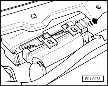
The automatic gearbox control unit -J217- is located at centre right of plenum chamber.
   
–  Switch off the ignition, unlock the multi-pin connector in -direction of arrow- and remove from the control unit.
  S01-0078
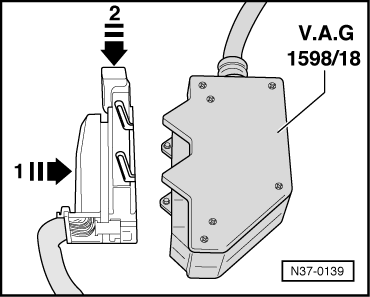
–  Plug test box -V.A.G 1598/18- into the multi-pin connector -1- and lock in direction of arrow -2-.
The test box e.g. -V.A.G 1598/18- allows to check the wiring according to the Current Flow Diagram.
  N37-0139
–  After the electrical test, insert the multi-pin connector on the automatic gearbox control unit -J217 - and lock -arrow-.
  Note
When inserting make sure the guides -1- and -2- are placed on the control unit pins.
  S01-0079
Multi-pin connector (plug connector 68-pin) of the control unit -J217- (bushes on -V.A.G. 1598/18-)
1-Earth (terminal 31)35-not assigned 
2-not assigned36-not assigned
3-CAN databus1)37-not assigned
4-not assigned38-not assigned
5-not assigned39-not assigned
6-Gearbox oil temperature sender -G93-40-Multi-function switch -F125-
7-not assigned41-Accelerator pedal value of the engine control unit2)
8-not assigned42-not assigned
9-Solenoid valve 3 -N90-43-Vehicle speed sender -G68- (screening)
10-Solenoid valve 7 -N94-44-Gearbox speed sender -G38- (screening)
11-Parking/Neutral signal45-Power supply (terminal 30)
12-Deactivation of the air conditioning system at kick-down46-not assigned
13-Ignition angle retardation/injection rate retardation2)47-Solenoid valve 4 -N91-
14-not assigned48-not assigned
15-Brake light switch -F- signal voltage49-not assigned
16-Kick-down switch -F8-50-not assigned
17-not assigned51-not assigned
18-Multi-function switch -F125-52-not assigned
19-Engine speed signal2)53-not assigned
20-Vehicle speed sender -G68-54-Solenoid valve 2 -N89-
21-Gearbox speed sender -G38-55-Solenoid valve 1 -N88-
22-Supply voltage solenoid valve 6 -N93-56-Solenoid valve 5 -N92-
23-Power supply (terminal 15)57-Selector lever position indicator
24-K cable of diagnosis58-Solenoid valve 6 -N93-
25-CAN databus1)59-not assigned
26-not assigned60-not assigned
27-not assigned61-Supply voltage for cruise control system2)
28-not assigned62-Multi-function switch -F125-
29-Selector lever lock solenoid -N110 -63-Multi-function switch -F125-
30-not assigned64-not assigned
31-not assigned65-Vehicle speed sender -G68-
32-not assigned66-Gearbox speed sender -G38-
33-not assigned67-Supply voltage for the solenoid valves
34-not assigned68-not assigned

1) Only for automatic gearbox with data bus (CAN databus) ⇒ current flow diagram as of model year 1998. This line is not assigned for gearboxes without data bus ⇒ current flow diagram as of model year 1997.
2) Only for automatic gearbox without data bus (CAN databus) ⇒ current flow diagram as of model year 1997. This line is not assigned for gearboxes with data bus ⇒ current flow diagram as of model year 1998.
Overview of test steps (multi-pin connector 68-pin)
t  Only perform the test steps listed per component in the fault table and the measured value block.
   
Component to be tested Component to be tested 
Power supply of automatic gearbox control unit -J217 -
–  Perform test step 1
Solenoid valve 5 -N92-
–  Perform test step 10
Selector lever lock solenoid -N110-
–  Perform test step 2 and 13
Solenoid valve 6 -N93-
–  Perform test step 11
Brake light switch -F-
–  Perform test step 3
Solenoid valve 7 -N94-
–  Perform test step 12
Multi-function switch -F125-
–  Perform test step 4 and 5
Kick-down switch -F8-
–  Perform test step 14
Solenoid valve 1 -N88-
–  Perform test step 6
Vehicle speed sender -G68-
–  Perform test step 15 and 16
Solenoid valve 2 -N89-
–  Perform test step 7
Gearbox speed sender -G38-
–  Perform test step 17 and 18
Solenoid valve 3 -N90-
–  Perform test step 8
Gearbox oil temperature sender -G93-
–  Perform test step 19
Solenoid valve 4 -N91-
–  Perform test step 9
CAN databus
–  Perform test step 20


Test table > < Check "two-line bus system”