
Octavia Mk1
 Note
Note
|
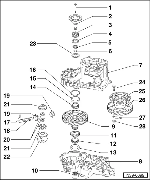
| 1 - | Screw, 25 Nm |
| q | screw to threaded connector to attach the flange shaft (⇒ Pos. 20) |
| 2 - | Flange shaft |
| q | with hole for conical screw |
| q | removing and installing → Chapter |
| 3 - | Pressure spring for flange shaft |
| q | fitted behind flange shaft |
| 4 - | Thrust washer |
| q | Fitting position: Flange to pressure spring, leg to conical ring |
| 5 - | Conical ring |
| q | with slots for thrust washer catch |
| q | Fitting position: Cone towards differential gear housing |
| 6 - | Circlip |
| q | holds the conical ring, stop disc and pressure spring in position when the flange shaft is removed |
| 7 - | Gearbox housing |
| 8 - | Clutch housing |
| 9 - | Differential gear housing |
| q | with riveted pinion for final drive |
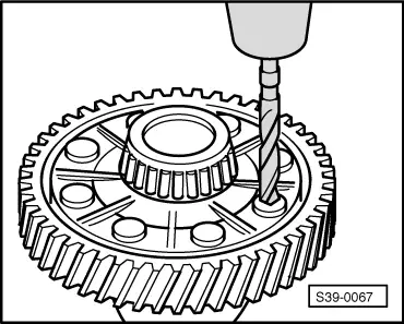
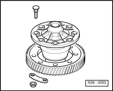
| q | when replacing the final drive pinion bore out the rivet heads → Fig. |
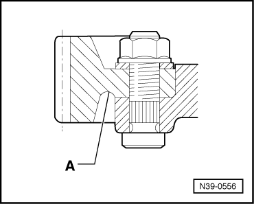
| q | Secure pinion for final drive with screws → Fig. |
| 10 - | Coupling sleeve to angle gearbox |
| q | pressed onto differential housing |
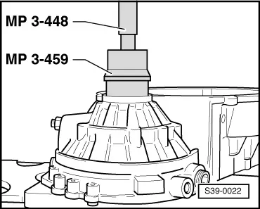
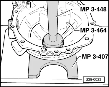
| q | pulling off and pressing on only with the differential housing removed |
| q | remove → Fig. |
| q | pressing on → Fig. |
| 11 - | Drive wheel for speedometer |
| q | before pressing on the inner ring place it on the differential gear housing up to the stop |
| 12 - | Inner ring/tapered-roller bearing |
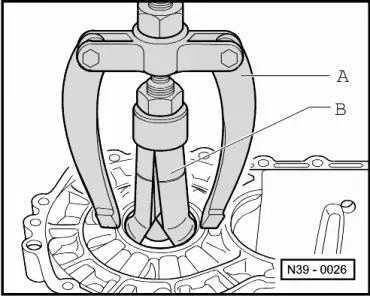
| q | before removal, pull off coupling sleeve (⇒ Pos. 10) |
| q | remove → Fig. |
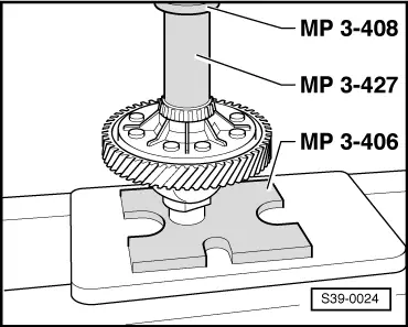
| q | pressing on → Fig. |
| 13 - | Outer ring/tapered-roller bearing |
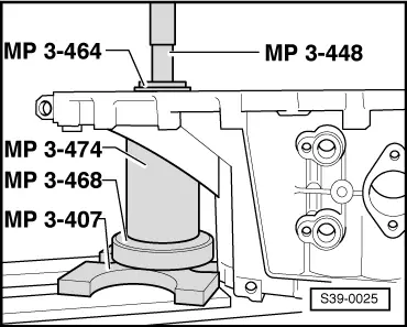
| q | extracting → Fig. |
| q | installing → Fig. |
| 14 - | Inner ring/tapered-roller bearing |
| q | remove → Fig. |
| q | pressing on → Fig. |
| 15 - | Outer ring/tapered-roller bearing |
| q | extracting → Fig. |
| q | installing → Fig. |
| 16 - | Adjusting washer |
| q | for the differential gear |
| q | Determine thickness → Chapter |
| 17 - | Tensioning sleeve |
| q | to secure the differential bevel gear shaft |
| q | removing and installing → Fig. |
| 18 - | Differential bevel gear shaft |
| q | drive out with -MP3-510- |
| q | installing → Fig. |
| 19 - | Differential bevel gear small |
| q | installing → Fig. |
| 20 - | Threaded part |
| 21 - | Differential bevel gear large |
| q | installing → Fig. |
| 22 - | Stop disc compound |
| q | insert with gear oil |
| 23 - | Gasket ring |
| q | replace → Chapter |
| 24 - | Screw |
| 25 - | Differential gear housing |
| q | screwed to pinion for final drive → Fig. |
| 26 - | Pinion for final drive |
| q | series riveted |
| q | screw → Fig. |
| q | heat to 100 °C before fitting |
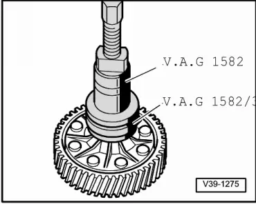
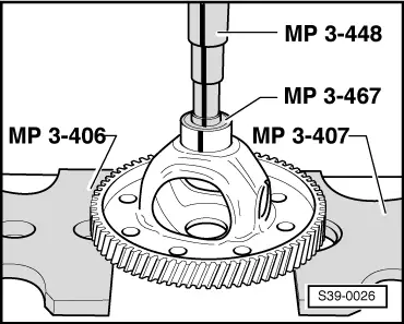
| q | pressing off → Fig. |
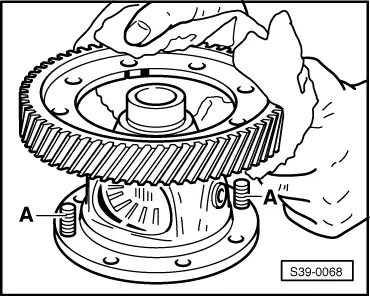
| q | Fitting position → Fig. |
| q | place on differential housing → Fig. |
| q | is paired with the output shaft, replace together |
| 27 - | Shim |
| 28 - | 70 Nm |
|
|
|
|
Note
|
|
|
|
|
|
Note
|
|
|
|
|
|
|
|
|
|
|
|
|

|
|
|
|
|