
Octavia Mk1
|
|
|
|
|
| new bearings | used bearings1) |
| 100…240 Ncm | 30…50 Ncm |
|
|
|
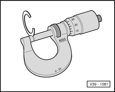
| Thickness (mm) | Spare part No. |
| 0,65 0,70 0,75 | 02C 409 280 02C 409 280A 02C 409 280B |
| 0,80 0,85 0,90 | 02C 409 280C 02C 409 280D 02C 409 280E |
| 0,95 1,00 1,05 | 02C 409 280F 02C 409 280G 02C 409 280H |
| 1,10 1,15 1,20 | 02C 409 280J 02C 409 280K 02C 409 280L |
| 1,25 1,30 1,35 1,40 | 02C 409 280M 02C 409 280N 02C 409 280P 02C 409 280Q |
|
|
|
|
|
|
|
|
|
|
|
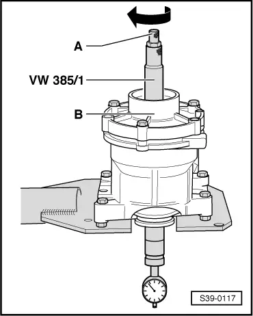
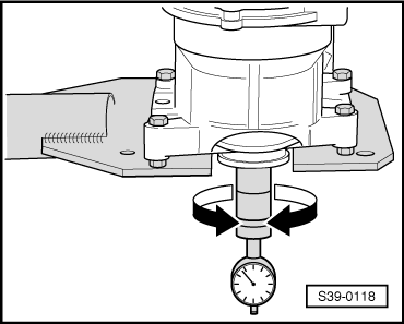
 Note
Note
|
|
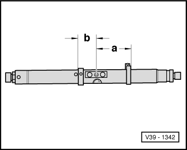
| e | - | determined value (maximum deflection) |
| r | - | Deviation (given on the head bevel gear in 1/100 mm) |
|
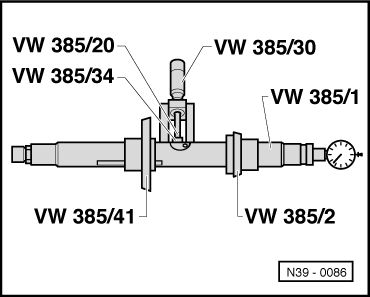
| on the dial gauge, value “e” is read off | 0.47 mm |
| deviation recorded on crown wheel “r” | + 0.33 mm |
| Thickness of the adjusting washer S3 | = 0.80 mm |
|
| Thickness (mm) | Spare part No. |
| 0,65 0,70 0,75 | 02C 409 114L 02C 409 114M 02C 409 114N |
| 0,80 0,85 0,90 | 02C 409 114P 02C 409 114Q 02C 409 114R |
| 0,95 1,00 1,05 | 02C 409 114S 02C 409 114T 02C 409 114AA |
| 1,10 1,15 1,20 | 02C 409 114AB 02C 409 114AC 02C 409 114AD |
| 1,25 1,30 1,35 | 02C 409 114AE 02C 409 114AF 02C 409 114AG |
| 1,40 1,45 1,50 | 02C 409 114AH 02C 409 114AJ 02C 409 114AK |
|