
Octavia Mk2
|
|
|
|
|
|
|
|
|

|
|
|
|
|
|
|
|
|
|
|
|
|
|
|
|
|
 Note
Note
|
|
Note
|
|
|
|
|
|
|
|
|
|
|
|
|
|
|
|
|
|
Note
Note
|
|
| Tightening torques: |
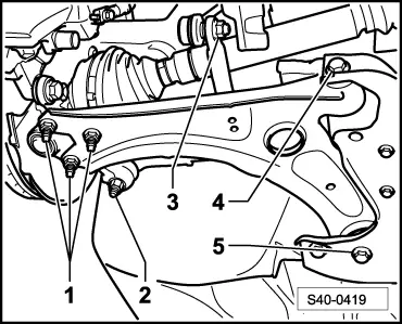
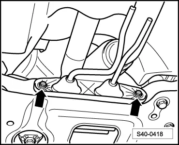
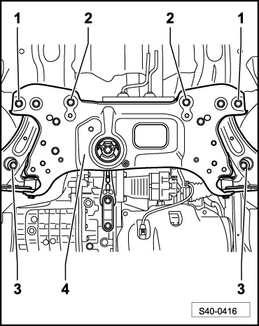
Assembly carrier to body
| 90 Nm + 180° | ||||
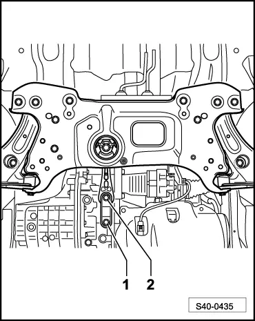
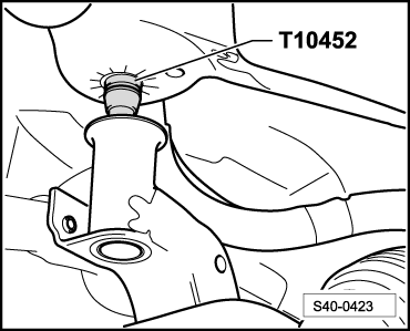
Coupling rod
| 65 Nm | ||||
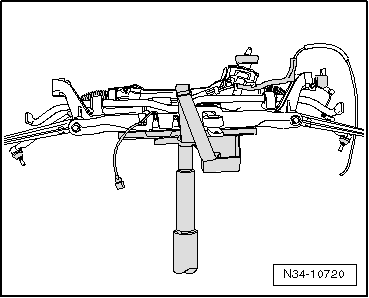
Universal joint to steering gear
| 20 Nm + 90° | ||||
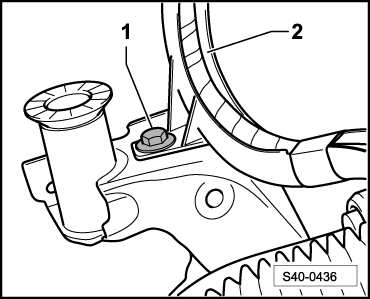
| Coupling rod for front left vehicle level sensor -G78- to track control arm | 9 Nm | ||||
| Wheel bolts | 120 Nm | ||||
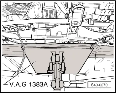
| Pendulum support to gearbox → Engine; Rep. gr.10 | |||||
| Bracket for exhaust system to assembly carrier → Engine; Rep. gr.26 | |||||