| Shock absorber to wheel-bearing housing | 180 Nm |
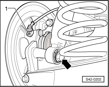
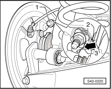
| Speed sensor to wheel-bearing housing | 8 Nm |
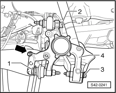
Trailing arm to wheel-bearing housing| t
| Determine → Anchor the fitting position of the trailing arm to the wheel-bearing housing before tightening the screws |
| 90 Nm +45° |
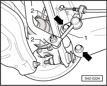
Top suspension arm to wheel-bearing housing| t
| Use new screws and nuts! |
| t
| Tighten in unladen weight position! → Chapter |
| 130 Nm +90° |
Bottom suspension arm to wheel-bearing housing| t
| Use new screws and nuts! |
| t
| Tighten in unladen weight position! → Chapter |
| 90 Nm +90° |
Track rod for rear axle to wheel-bearing housing| t
| Use new screws and nuts! |
| t
| Tighten in unladen weight position! → Chapter |
| 130 Nm +90° |
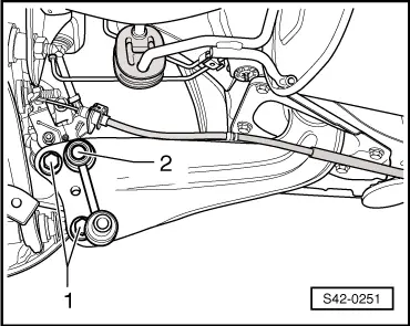
| Coupling rod | 45 Nm |
| Wheel bolts | 120 Nm |

 Note
Note