skoda Workshop Repair Guides

Skoda Workshop Service and Repair Manuals

Disconnect fuel distributor from intake manifold > < Fuel distributor - Summary of component
Removing and installing intake manifold with fuel distributor
Special tools and workshop equipment required
t  Oil filter wrench -3417 -
t  Socket insert -T10347-
  Note
t  If the intake manifold is replaced, the intake manifold flap potentiometer -G336- must be adapted → Vehicle diagnosis, testing and information system VAS 5051 to the engine control unit -J623 -.
t  
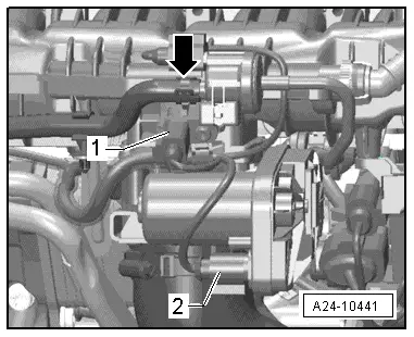
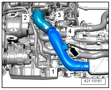
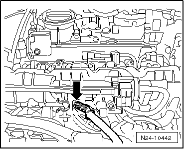
In order to reach the injection valves, the intake manifold with fuel distributor must be removed.
t  The combustion chamber gasket ring (Teflon gasket ring) and O-ring must be replaced.
Removing
  WARNING
The fuel system is under pressure! Before opening the high pressure of the injection system, the fuel pressure with a remaining pressure must be reduced → Chapter.
–  Observe all safety measures and notes for assembly work on the fuel, injection and ignition system as well as the rules for cleanliness → Chapter.
–  Remove the air filter housing → Chapter.
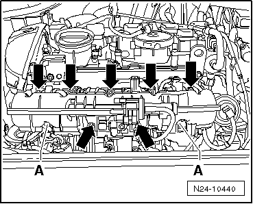
–  Clean the contact face from the intake manifold to the cylinder head.
   
–  Disconnect the vacuum line -arrow- to the activated charcoal filter system.
–  Unplug the connector from the following components:
t  Intake air temperature sender -G42--1-
t  Throttle valve control unit -J338--2-
t  Solenoid valve 1 for activated charcoal filter -N80-
t  Hall sender -G40-
  A24-10441
–  Disconnect the vacuum line -1- at the separation point -2- and remove the hose for crankcase ventilation -3-.
  N24-10444
–  Unscrew screws -arrows- of the fuel feed line and place the line to the side.
  A24-10442
–  Unscrew the union nut of the fuel line -lower arrow- to the high pressure pump.
  A24-10443
–  Disconnect the vacuum line -arrow- from the intake manifold flap valve -N316-.
  A24-10555
–  Unscrew the screws -arrows- of the coolant line at intake manifold.
  A24-10446
–  Disconnect plug from fuel pressure sender -G247--1-.
–  Remove the sound dampening system → Body Work; Rep. Gr.50.
  A24-10445
–  Slacken clamps -1 and 2- and remove charge air hose.
  A21-10051
–  Loosen clamp -2-.
–  Disconnect plug -arrow- from charge pressure sender -G31-.
–  Loosen clamp at charge air pipe.
–  Unscrew screws -1- and -4- and remove the charge air pipe with the hose to the bottom.
  A21-10161
–  Disconnect the plug connections -1…3- and unscrew the bracket from the intake manifold.
  A24-10427
–  Release nut -1-, release screw -2- and remove intake manifold support.
–  Unscrew the oil filter using the oil filter wrench -3417-.
–  Cover oil filter holder.
  A24-10447
–  Release the cable clip -arrows-.
  N24-10439
–  Release the cable -arrow- from the intake manifold.
  N24-10442
–  Unscrew nuts -A-.
–  Release screws -arrows- with socket insert -T10347-.
–  Carefully pull off the intake manifold with fuel distributor a little from the cylinder head.
  N24-10440
–  Unplug plug -arrow- from potentiometer for intake manifold flap -G336- and remove the intake manifold.
–  Seal intake passages with a clean cloth.
  Note
The injection valves can remain stuck in the fuel distributor.
–  Disconnect fuel distributor from intake manifold → Chapter.
Install
l  The injection valves are seated in the cylinder head. Install injection valves → Chapter.
–  Push the intake manifold over the pin screws (left and right) onto the cylinder head.
  Note
Pay attention to correct fitting position of the injection valves and when positioning the intake manifold on the cable clip (below the intake manifold).
When installing the intake manifold, the intake manifold must again be slightly pulled off the cylinder head and if the injection valves remain stuck in the fuel distributor during this operation:
–  Pull out the injection valves once again from the fuel distributor and reinsert them into the cylinder head.
Further installation occurs in reverse order. Pay attention to the following:
  N24-10443
–  Clip in all catches when locking the cable clip onto the intake manifold.
Tightening torques:
t  Summary of components of intake manifold: → Chapter
t  Summary of components of fuel distributor: → Chapter
  N24-10439

Disconnect fuel distributor from intake manifold > < Fuel distributor - Summary of component